
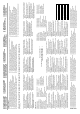
Specifications


Installation and operation manual
6
RXYQQ8~20T7Y1B
VRV IV System Air Conditioner
4P345099-1 – 2013.04
5. Overview of unit
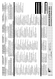
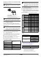
5.1. Opening the unit
To gain access to the unit, front plates need to be opened as follows:
Once the front plates open, the electrical component box can be
accessed by removing the electrical component box cover as follows.
For service purposes, the push buttons on the main PCB need to be
accessed. To access these push buttons, the electrical component
box cover does not need to be opened. See "13. Making field
settings" on page 28.
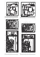
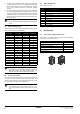
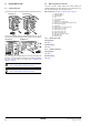
5.2. Main components in the unit
For all the models a piping diagram and outlook drawing are
available. Depending on the model type some components in the
main component list may not be existing in the unit.
Main components (see figure 1, figure 2, figure 3, figure 4)
1 Compressor (M1C)
2 Compressor (M2C)
3 Heat exchanger
4 Fan
5 Fan motor (M1F, M2F)
6 Accumulator
7 Expansion valve, main (Y1E)
8 Expansion valve, subcool heat exchanger (Y2E)
9 Subcool heat exchanger
10 Oil separator
11 Solenoid valve, oil accumulator (Y2S)
12 Solenoid valve, oil1 (Y3S)
13 Solenoid valve, oil2 (Y4S)
14 4-way valve, main (Y1S)
15 Electrical component box
16 Service port, refrigerant charge
17 Stop valve, liquid
18 Stop valve, gas
5.2.1. RXYQQ* (8~12 HP)
Piping diagram
See figure 1.
Outlook drawing
See figure 3.
5.2.2. RXYQQ* (14~20 HP)
Piping diagram
See figure 2.
Outlook drawing
See figure 4.
DANGER: Electrical shock
See "2. General safety precautions" on page 2.
DANGER: Do not touch piping and internal parts.
See "2. General safety precautions" on page 2.
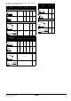
RXYQQ14~20RXYQQ8~12
14x14x
RXYQQ14~20RXYQQ8~12
2x
6x