
Specifications


RXYQQ8~20T7Y1B
VRV IV System Air Conditioner
4P345099-1 – 2013.04
Installation and operation manual
1
Installation manual
Contents Page
Installation manual .......................................................................... 1
1. Definitions .................................................................................. 1
1.1. Meaning of warnings and symbols................................................. 1
1.2. Meaning of used terms................................................................... 2
2. General safety precautions ........................................................ 2
3. Introduction ................................................................................ 2
3.1. General information........................................................................ 2
3.2. Combination and options ............................................................... 3
3.3. Indoor capacity range..................................................................... 4
3.4. Scope of the manual ...................................................................... 4
3.5. Model identification ........................................................................ 4
4. Accessories................................................................................ 4
4.1. Accessories supplied with this unit................................................. 4
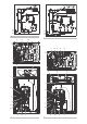
5. Overview of unit ......................................................................... 6
5.1. Opening the unit............................................................................. 6
5.2. Main components in the unit .......................................................... 6
5.3. Main components in the electrical component box ........................ 7
6. Selecting an installation location................................................ 7
6.1. General precautions on installation ................................................ 7
6.2. Weather related precautions .......................................................... 8
6.3. Selecting a location in cold climates .............................................. 8
7. Dimensions and service space .................................................. 9
7.1. Dimensions of outdoor unit............................................................. 9
7.2. Service space................................................................................. 9
8. Inspecting, handling and unpacking the unit............................ 10
8.1. Inspection..................................................................................... 10
8.2. Handling ....................................................................................... 10
8.3. Unpacking .................................................................................... 10
8.4. Installing the unit .......................................................................... 10
8.5. Method for removing transportation stay.......................................11
9. Refrigerant pipe size and allowable pipe length ...................... 11
9.1. General information.......................................................................11
9.2. Selection of piping material ...........................................................11
9.3. Selection of piping size ................................................................ 12
9.4. Selection of refrigerant branch kits............................................... 13
9.5. System piping (length) limitations................................................. 13
9.6. Multi system piping installation..................................................... 15
10. Precautions on refrigerant piping............................................. 16
10.1. Caution for brazing....................................................................... 16
10.2. Connecting the refrigerant piping ................................................. 17
10.3. Guidelines for handling stop valve ............................................... 19
10.4. Leak test and vacuum drying ....................................................... 19
11. Pipe insulation.......................................................................... 21
12. Electrical wiring work ............................................................... 21
12.1. Precautions on electrical wiring work ........................................... 21
12.2. Internal wiring – Parts table.......................................................... 22
12.3. System overview of field wiring .................................................... 23
12.4. Opening and closing the electrical component box...................... 23
12.5. Requirements............................................................................... 24
12.6. Routing......................................................................................... 24
12.7. Connection ................................................................................... 27
13. Making field settings ................................................................ 28
13.1. Accessing the push buttons on the logic board............................ 28
13.2. Operating the push buttons and DIP switches on the logic
board ............................................................................................ 29
13.3. Connecting the PC configurator to the outdoor unit ..................... 30
14. Charging refrigerant................................................................. 30
14.1. Precautions .................................................................................. 30
14.2. Important information regarding the refrigerant used................... 31
14.3. Calculating the additional refrigerant charge................................ 31
14.4. Method for adding refrigerant....................................................... 32
15. Start-up and configuration........................................................ 36
15.1. Checks before initial start up........................................................ 36
15.2. Monitoring function and field settings........................................... 37
15.3. Energy saving and optimum operation......................................... 40
15.4. Test operation............................................................................... 43
15.5. Malfunction code list..................................................................... 44
16. Operation of the unit ................................................................ 46
17. Maintenance and service ......................................................... 46
17.1. Maintenance introduction............................................................. 46
17.2. Service precautions...................................................................... 46
17.3. Service mode operation ............................................................... 47
18. Caution for refrigerant leaks..................................................... 47
18.1. Introduction .................................................................................. 47
18.2. Maximum concentration level....................................................... 47
18.3. Procedure for checking maximum concentration ......................... 47
19. Disposal requirements ............................................................. 48
20. Unit specifications .................................................................... 48
20.1. General technical specifications................................................... 48
20.2. Electrical specifications ................................................................ 49
Operation manual .......................................................................... 50
Thank you for purchasing this Daikin VRV IV system.
The original instructions are written in English. All other languages
are translations of the original instructions.
1. Definitions
1.1. Meaning of warnings and symbols
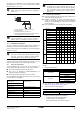
Warnings in this manual are classified according to their severity and
probability of occurrence.
RXYQQ8T7Y1B RXYQQ16T7Y1B
RXYQQ10T7Y1B RXYQQ18T7Y1B
RXYQQ12T7Y1B RXYQQ20T7Y1B
RXYQQ14T7Y1B
VRV IV System Air Conditioner
Installation and
operation manual
CAREFULLY READ THESE INSTRUCTIONS BEFORE
INSTALLATION. THEY WILL TELL YOU HOW TO
INSTALL AND HOW TO CONFIGURE THE UNIT
PROPERLY. KEEP THIS MANUAL IN A HANDY PLACE
FOR FUTURE REFERENCE.
DANGER
Indicates an imminently hazardous situation which, if not
avoided, will result in death or serious injury.
WARNING
Indicates a potentially hazardous situation which, if not
avoided, could result in death or serious injury.
CAUTION
Indicates a potentially hazardous situation which, if not
avoided, may result in minor or moderate injury. It may also
be used to alert against unsafe practices.
NOTICE
Indicates situations that may result in equipment or
property-damage accidents only.
INFORMATION
This symbol identifies useful tips or additional information.