
Specifications


RXYQQ8~20T7Y1B
VRV IV System Air Conditioner
4P345099-1 – 2013.04
Installation and operation manual
3
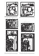
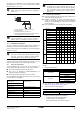
The outdoor unit is designed to work in heating mode at ambient
temperatures from –20°C to 21°C and in cooling mode at ambient
temperatures from –5°C to 43°C.
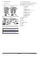
1 VRV IV replacement heat pump outdoor unit
2 Refrigerant piping
3 VRV direct expansion (DX) indoor unit
4 User interface (dedicated depending on indoor unit type)
5 Cool/Heat changeover remote control switch
3.2. Combination and options
The VRV IV replacement heat pump system can be combined with
several types of indoor units and is intended for R410A use only.
For an overview which units are available you can consult the product
catalogue for VRV IV.
An overview is given indicating the allowed combinations of indoor
units and outdoor units. Not all combinations are allowed. They are
subject to rules mentioned in the technical engineering data.
3.2.1. Indoor unit combinations
In general following type of indoor units can be connected to a
VRV IV replacement heat pump system. The list is non-exhaustive.
VRV direct expansion (DX) indoor units for R410A.
AHU (air to air applications): EKEXV-kit+EKEQ-box are
required, depending on application.
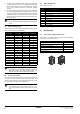
VRV direct expansion (DX) indoor units for non-R410A.
List of compatible (non-R410A) VRV DX indoor units: model series
as in table below or newer ONLY.
Other non-R410A indoor units are NOT allowed.
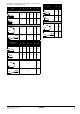
3.2.2. Outdoor unit combinations
Multi unit combinations can never contain other models than one
of the multi modules (RXYQQ8~20).
Standard combinations for VRV IV replacement heat pump
system are as indicated in table below, where RXYQQ22~42
consists of several RXYQQ8~20 modules in the horsepower
class as indicated.
Other combinations than these here below are prohibited.
To install the outdoor unit, the following optional parts are also
required.
1 Refrigerant branching kit.
For the selection of the optimal branching kit, please refer to
"9.4. Selection of refrigerant branch kits" on page 13.
2 Outdoor unit multi connection piping kit.
3 In order to control the cooling or heating operation from a central
location, the following option can be connected:
- Cool/heat change over switch: KRC19-26A.
- Cool/heat change over PCB: BRP2A81
- With optional fixing box for the switch: KJB111A.
NOTICE
Design of the system must not be done at temperatures
below –15°C.
INFORMATION
Not all combinations of indoor units are allowed, for
guidance, see "3.2. Combination and options" on page 3.
NOTICE
To be sure your system setup (outdoor unit+indoor unit(s))
will work, you have to consult the latest technical
engineering data for VRV IV replacement heat pump.
Model series Type
FXYBP_K7V19 Conceiled ceiling
FXYSP_KA7V19
FXYMP_KV19
FXYCP_K7V19 2-way blow ceiling mounted
FXYFP_KB7V19 4-way blow ceiling mounted
FXYHP_KVE9 Ceiling suspended
FXYL(M)P_KV19 Floorstanding
FXYKP_KV19 Ceiling mounted corner cassette
FXYAP_KV19 Wall mounted
44
332
5
1
INFORMATION
A combination of R410A VRV DX indoor units with
non-R410A VRV DX indoor units will block the system.
Such combinations cannot be used. Either all VRV DX
indoor units are non-R410A type (as listed above) or
R410A type.
8 HP 10 HP 12 HP 14 HP 16 HP 18 HP 20 HP
Heat pump
RXYQQ8* 1
RXYQQ10* 1
RXYQQ12* 1
RXYQQ14* 1
RXYQQ16* 1
RXYQQ18* 1
RXYQQ20* 1
Multi combination
with 2 outdoor units
RXYQQ22* 1 1
RXYQQ24* 1 1
RXYQQ26* 1 1
RXYQQ28* 1 1
RXYQQ30* 1 1
RXYQQ32* 2
RXYQQ34* 1 1
RXYQQ36* 1 1
Multi combination
with 3 outdoor units
RXYQQ38* 1 1 1
RXYQQ40* 1 1 1
RXYQQ42* 1 2
Description Model name
Refnet header
KHRQ22M29H
KHRQ22M64H
KHRQ22M75H
Refnet joint
KHRQ22M20T
KHRQ22M29T9
KHRQ22M64T
KHRQ22M75T
Number of outdoor units connected
2 3
BHFQ22P1007 BHFQ22P1517