INSTALLATION MANUAL Split system air conditioner RZQ200C7Y1B RZQ250C7Y1B
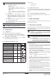
1 B B c Aa 1 2 3 4 c bC Aa e e d D c a e f f a c a b e C d b f f A b h2 B c e a C e d b d D h1 500 B c 1500 d D A bC d D 1 4 5 ≥1500 ≥1000 ≥10 00 4 1 A B 2 4 0 150 ≥ 3 1 ≥1500 1 2 5 3 (mm) 2 5 1 765 5 2 3 3 3 2 722-737 3 ≥66 ≥66 2 3 4 5 7 6 A B 1 2 3 1 8 4 8 6 8 5 3 2 8 7 8 11 10 9 8 8 9 6 7 8 9 10 11 L2 H1 6 H2 L1 L3 H1 L1 2 3 1 1 8 9 12 2 10 13 5 3 11 14 L4 4 3 15 10 8 7 9 L2 H2 H1 L1 L6 L4
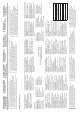
CE - DECLARACION-DE-CONFORMIDAD CE - DICHIARAZIONE-DI-CONFORMITA CE - ¢H§ø™H ™YMMOPºø™H™ 01 *** 02 *** 03 *** 04 *** 05 *** 06 *** Daikin Europe N.V. is authorised to compile the Technical Construction File. Daikin Europe N.V. hat die Berechtigung die Technische Konstruktionsakte zusammenzustellen. Daikin Europe N.V. est autorisé à compiler le Dossier de Construction Technique. Daikin Europe N.V. is bevoegd om het Technisch Constructiedossier samen te stellen. Daikin Europe N.V.
настоящее заявление: 19 • Maksimalni dovoljeni tlak (PS): (bar) • Minimalna/maksimalna dovoljena temperatura (TS*): * TSmin: Minimalna temperatura na nizkotlačni strani: (°C) * TSmax: Nasičena temperatura, ki ustreza maksimalnemu dovoljenemu tlaku (PS): (°C) • Hladivo: • Nastavljanje varnostne naprave za tlak: (bar) • Tovarniška številka in leto proizvodnje: glejte napisno ploščico 20 • Maksimaalne lubatud surve (PS): (bar) • Minimaalne/maksimaalne lubatud temperatuur (TS*): * TSmin
RZQ200C7Y1B RZQ250C7Y1B CONTENTS Page 1. Safety considerations................................................................. 1 2. Introduction ................................................................................ 2 2.1. 2.2. 2.3. 2.4. Installation manual Split system air conditioner 1. SAFETY CONSIDERATIONS The precautions listed here are divided into the following two types. Both cover very important topics, so be sure to follow them carefully. Combination............................
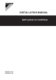
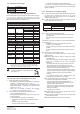
Refer to figure 2. Precautions for R410A ■ The refrigerant requires strict cautions for keeping the system clean, dry and tight. - Clean and dry Foreign materials (including mineral oils or moisture) should be prevented from getting mixed into the system. - Tight Read "7.6. Precautions on refrigerant piping" on page 5 carefully and follow these procedures correctly. ■ Since R410A is a mixed refrigerant, the required additional refrigerant must be charged in its liquid state.
Make sure that the air inlet and outlet of the unit are not positioned towards the main wind direction. Frontal wind will disturb the operation of the unit. If necessary, use a windscreen to block the wind. 5. INSPECTING 9 Do not install or operate the unit on locations where air contains high levels of salt, like e.g. in the vicinity of oceans.
■ ■ ■ ■ 7.1. ■ If the unit is to be installed on a roof, check the strength of the roof and its drainage facilities first. Construction material: phosphoric acid deoxidized seamless copper for refrigerant. ■ Temper grade: use piping with temper grade in function of the pipe diameter as listed in table below. ■ The pipe thickness of the refrigerant piping should comply with relevant local and national regulations. The minimal pipe thickness for R410A piping must be in accordance with the table below.
7.3. Selection of branch pipe Twin KHRQ22M20TA Triple KHRQ250H Double twin KHRQ22M20TA (3x) • Check the contamination inside the existing piping. If you cannot meet all these requirements, the existing pipes must be cleaned or replaced after removing the air conditioning units to be replaced. 7.6. 7.4. Precautions on refrigerant piping Allowable pipe length and height difference ■ See the table below concerning lengths and heights. Refer to figures 8, 9, 12 and 13.
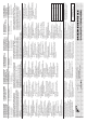
7.7. Connecting the refrigerant piping Precautions when connecting field piping. 1 Installation of refrigerant branching kit. (See figure 14) For installation, refer to the installation manual delivered with the kit. Follow the conditions listed below: Mount the refnet joint so that it branches either horizontally (see view A) or vertically. 1 2 ■ Perform brazing at the gas stop valve before brazing at the liquid stop valve. ■ Add brazing material as shown in the figure.
5 6 For installation of the refrigerant branching kit (Refnet), refer to the installation manual delivered with the kit. Pipe connection State of the valves A and B and the stop valve Be sure to perform a nitrogen blow when brazing. (Brazing without performing nitrogen replacement or releasing nitrogen into the piping will create large quantities of oxidized film on the inside of the pipes, adversely affecting valves and compressors in the refrigerating system and preventing normal operation.
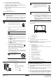
■ If there is a possibility that condensation on the stop valve might drip down to the indoor side through gaps in the insulation and piping because the outdoor unit is located higher than the indoor unit this must be prevented by sealing up the connections. See figure 20. Tightening torque (N•m) (Turn clockwise to close) stop valve size Shaft (valve body) Cap (valve lid) 13.5~16.5 33~40 18~22 50~60 1 Liquid line stop valve Ø9.5 5.4~6.6 2 Gas line stop valve Ø12.7 8.1~9.
Precaution for servicing 9 See the examples below for a clear understanding. Example 1 When performing service on the unit requiring the refrigerant system to be opened, refrigerant must be evacuated according to local regulations. This unit requires additional charging of refrigerant according to the length of pipe connected at the site. Charge the refrigerant to the liquid pipe in its liquid state through the serviceport of the liquid stop valve.
Total charging weight of the refrigerant (after a leak, etc.) ■ Charge the liquid refrigerant with the cylinder in upright position. The total charging amounts relate to the refrigerant piping length as in "Maximum total one way piping length" of the table in paragraph "7.4. Allowable pipe length and height difference" on page 5, the factory charging amount is mentioned on the nameplate label. For the total charging amount refer to the additional refrigerant charge sticker mounted on the unit.
8. FIELD ■ ■ ■ WIRING All field wiring and components must be installed by a licensed electrician and must comply with relevant local and national regulations. The field wiring must be carried out in accordance with the wiring diagrams and the instructions given below. Be sure to use a dedicated power circuit. Never use a power supply shared by another appliance. This can lead to electrical shock or fire.
...............Field wiring ■ Select the power supply cable in accordance with relevant local and national regulations. ■ Wire size must comply with the applicable local and national code. ..........................Terminal ■ Specifications for local wiring power cord and branch wiring are in compliance with IEC60245. ..........................Protective earth (screw) ■ WIRE TYPE H05VV(*) *Only in protected pipes (use H07RN-F when protected pipes are not used). NOTE .....................
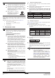
8.5. Examples Precautions when installing power wiring System example (See figure 22) 1 Field power supply 2 Main switch 3 Earth leakage breaker 4 Fuse 5 Remote controller Use round pressure terminals for connections to the power terminal block. When none are available, follow the instructions below. ■ Do not connect wiring of different thicknesses to the power terminal block. (Slack in the power wiring may cause abnormal heat.
Picking power line and transmission line Never connect 400 V to the terminal block of the interconnecting wiring. Doing so will break the entire system. ■ Be sure to let the power line and the transmission line pass through a conduit hole. ■ ■ Pick the power line from the upper hole on the left side plate, from the front position of the main unit (through the conduit hole of the wiring mounting plate) or from a knock out hole to be made in the unit's bottom plate.
9.2. Checks before initial start-up Location of the DIP switches, LEDs and buttons Note that during the first running period of the unit, required power input may be higher than stated on the nameplate of the unit. This phenomenon originates from the compressor that needs elapse of a 50 hours run in period before reaching smooth operation and stable power consumption.
9.4. Test operation Test operation from outdoor PCB BS4 test button After turning on the power supply, the unit cannot be started until the H2P initialisation LED goes off (maximum 12 minutes). NOTE ■ Check the stop valves Make sure to open the gas and liquid line stop valves. ■ For details on test operation, refer to the indoor unit installation manual. Pre-run checks 3 Make sure to set the remote controller to fan mode, press the BS1 MODE button first and then press the operation switch.
Setting mode 2 10. SERVICE The H1P LED is on. Vacuuming method Setting procedure At the first installation, this vacuuming is not required. It is required only for repair purposes. 1 Push the BS2 SET button according to the required function (A~E). The LED indication that matches the required function is shown below in the field marked : 1 When the unit is at standstill and under the setting mode 2, set the required function B (refrigerant recovery operation/ vacuuming operation) to ON (ON).
Maximum concentration level 2 Calculate the smallest room volume (m3) In a case such as the following, calculate the volume of (A), (B) as a single room or as the smallest room. The maximum charge of refrigerant and the calculation of the maximum concentration of refrigerant is directly related to the humanly occupied space in to which it could leak. A. Where there are no smaller room divisions B.
19 20 21 1 1 4 2 3 19 6 4 5 6 4 1 1 2 4 A 3 2 22 L1 L2 L3 2 3 5 5 3 3 5 6 7 N 8 4 9 3 5 20 21 22 24 23 1 10 2 5 3 6 6 9 4 3 2 11 6 3 2 7 1 23 NOTES 8 24 7 4
Copyright 2006 Daikin 4PW34720-1G – 07.