
Manual


Model 5-025, 5-050, 5-075 & 5-150
1
INSTRUCTIONS AND PARTS LIST FOR
Models 5-025, 5-050, 5-075, and 5-150
Elec-Draulic I Presses
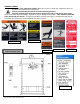
WARNING LABELS
To the left is the safety Alert symbol. When you see these safety alert symbols on your press,
be alert to the potential for personal injury.
Follow recommended precautions and safe operating practices.
SETTING UP THE PRESS FOR OPERATION
For shipping convenience some of the parts are not assembled. Assemble these parts in the following order:
1. Bolt the base angles to uprights using four bolts and nuts, which are provided. Make sure base
angles are against stops on uprights.
NOTE: The press should set on a level floor with the base angles touching the floor at all
points. Use shims where necessary.
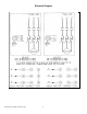
2. Motor starter box is mounted on left upright. Have electrician connect power to motor starter. Pump
can rotate in either direction.
3. Oil Requirements: Fill reservoir thru street elbow at back of press with Mobil DTE oil No. 24 or
equivalent. NOTE: Oil level may be checked (with ram up) by removing the 1/8” NPT pipe plug
on the right side of reservoir near the front. Replace plug before operating the press.
Model 5-025 uses 6 quarts
Model 5-050 uses 8 quarts
Model 5-075 uses 10 quarts
Model 5-150 uses 20 quarts
4. Prime pump by removing the plug in the top of the pump opposite the intake line and allow the oil
levels in the reservoir and pump to equalize. Fill pump with additional oil (if required), replace plug
making sure seal is tight, and start motor.
5. Attach nose piece to ram by inserting shank into ram and tightening the set screw.
CAUTION! Place the hoist crank on the lift drum shaft. Turn the hoist crank to relieve
the pressure on the table pins. Keeping tension on the hoist crank, remove the table pins one
at a time. After removing the tables pins, turn the crank running the table channels from top to
bottom. Check to make sure the cable is tracking correctly. The cable should be on each of
the two upper pulleys and should track back and forth on the cable drum. Always place table
pins under the table channels before releasing the hoist crank when positioning the table
channels for cable tracking, servicing, or set-up for desired work opening. If a tracking
problem exists, contact the Dake factory for instructions. Be sure all table pins are fully
inserted in place before applying pressure. Always remove or release pressure on the cable
before pressure is applied.
OPERATIONS
WARNING: DO NOT OVERSTROKE THE RAM. Overstroking will cause premature seal failure.
Models 5-025, 5-050, & 5-075 have a 10-inch stroke. Model 5-150 has a 16-inch stroke.
The press has been completely tested at the factory and after setting up according to instructions above, the
press is ready for operation. However, it is necessary for the operator to acquaint themselves with the
controls.
1. Three screws (item 100) are used to lock the workhead in the desired position along head
channels.
2. The handcrank (item 19) is provided to raise or lower the table channels to the proper work height.
When desired height is obtained insert the table pins. Models 5-025 and 5-050 use 2 pins on each
side (4 total) and Models 5-075 and 5-150 use 3 pins on each side (6 total).