DAKE / JOHNSON VERTICAL BAND SAW Model F - 16 INSTRUCTION MANUAL Need band saw blades? Call Dake MODEL:F-16________________________ SERIAL NUMBER:___________________ DATE PURCHASED: _________________ 4/11/2007 DAKE (Division of JSJ) 724 Robbins Road Grand Haven, Michigan 49417 616.842.7110 Phone 800-937-3253 616.842.0859 Fax 800-846-3253 Web: www.dakecorp.com E-mail : customerservice@dakecorp.com technicalsupport@dakecorp.
WARNING! This machine must be wired by a qualified electrician. This machine is designed to be wired for the specified voltage with a tolerance of +/10%. If your voltage is outside this 10% it will require a transformer to obtain the correct voltage. Failure to do so may affect warranty, if damage occurs from improper wiring or electrical supply. FOREWORD These instructions cover the installation and operation of vertical band saw.
Machine Features F - 16 WARNING!!! The machine table must NOT be used as a lifting point. Damage to the saw could occur. UNLOADING: Remove the shrink-wrap covering the machine, careful not to damage painted surfaces. Carefully inspect the machine for physical damage. If damage is noted, notify the truck line at once. They may require inspection, and that a claim be filed. Check that all standard accessories are with the machine. Some accessories may be boxed or placed behind the rear access door.
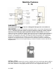
protective coating on machined metal surfaces. These surfaces should be cleaned with the appropriate solvent and then coated with a light film of oil to prevent rust from forming. F-16 Foot Print Below measurement is in inches .98 23.6 17.7 14.9 3.93 19.0 .39 27.
ELECTRICAL: To wire this machine there is a small box on the back side of the machine, this is where the machine is wired in (see illustration below). warning!!! Power must be locked out before removing any electrical panel. WARNING! This machine must be wired by a qualified electrician. This machine is designed to be wired for the specified voltage labeled below with a tolerance of +/- 10%. If your voltage is outside this 10% it will require a transformer to obtain the correct voltage.
To change the machine from 1 phase to 3 phase follow the instructions below. 220 Volt 1 Phase How to wire for 220 Volt 1 Phase: 1. Connect one lead to L1 2. Connect one lead to L3; this must be the neutral wire. 3. Connect ground wire to ground 220 Volt 3 Phase How to wire for 220 Volt 3 Phase 1. Connect each wire to L1, L2, L3 2. Connect ground wire to ground 440 Volt 3 Phase To use 440 volt on this machine a step down transformer is required.
WARNING!!! Electrical supply must be locked out when changing the blade. Blade selection is based on the many factors and complexity of the work to be cut. The blade placed on the band wheels with teeth facing toward the operator and down toward the top of the worktable. Tension the blade to remove slack. Rotate the wheels by pushing the jog button to ensure tracking is correct, and blade will not “pop” off when machine is started. If tracking is incorrect, adjust before starting machine.
BLADE TENSIONING The blade indicator is located inside the upper wheel compartment, on the lower left side of the idle wheel. (See picture above) The indicator has an arrow mounted on the horizontal plane, with a corresponding scale for blade tensioning. The scale has two legends, one reads inches from 0 - 1”, and the second reads mm 0 - 25 mm. This allows tensioning either standard or metric blade widths. With out tension on the blade, the indicator should read zero.
The blade should always be inspected before installing on the machine. Things to look for should be the smoothness on the sides and back edge of the weld, look for any missing teeth, or impacted chips. The blade guides may now be selected and inserted into both the upper and lower guide holders. Proper adjustment of these guides takes place when they form a complete “V” shape (see graphic above) and support the blade equally on each side.
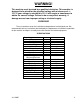
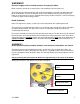
MATERIAL SHAPE MATERIAL SHAPE MATERIAL SHAPE INCHES TOOTH SELECTION TOOTH SELECTION TOOTH SELECTION 0 .1 .2 .3 .4 .5 .6 .7 .8 .9 1 1 1/4 1 1/2 1 3/4 2 2 1/4 2 1/2 2 3/4 3 3 1/4 3 1/2 3 3/4 4 5 6 7 8 9 10 11 14 / 18 14 / 18 14 / 18 10 / 14 8 / 12 8 / 12 6 / 10 6 / 10 5/8 5/8 5/8 4/6 4/6 4/6 4/6 4/6 3/4 3/4 3/4 3/4 3/4 3/4 3/4 2/3 2/3 2/3 1.4 / 2.5 1.4 / 2.5 1.4 / 2.5 1.4 / 2.
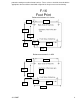
Machine Operation Look over the control panel to get familiar with the buttons before operating (see picture below). Digital Tach read out Blade Speed Emergency Stop Run / Jog Power Start Saw Start Saw Stop Jog Main Power Switch Digital Tachometer Read out: This will show the blade speed in surface feet per minute. Blade Speed: This controls the speed of the blade 50-550 sfm. Emergency Stop: When this button is pushed it will shut all power off to all components.
MACHINE OPERATION To operate the machine, do the following: 1. Turn the main power on, and then push the saw power button. 2. Now turn the run jog button to run, and then push the saw start button. The saw blade will begin to move at the designated speed that is selected. 3. To change the blade speed, turn the blade speed knob to the desired speed by turning left or right. It will take about 3 seconds for the digital tac to read the correct speed. 4. To stop the saw blade push the saw blade stop button. 5.
ACCESSORIES Rip Fence Part number 81521 PROTRACTOR HEAD See figure 4 part number 75561 T-SLOTS T-slots are machined into the work table for your use of fixturing or other accessories. The dimensions of these T-slots are furnished to the right. How to program the frequency drive. 1. Please see the electrical print for the parameter list.
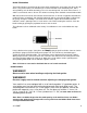
How to program the digital speed display (This is factory set and will only need to be programmed if the unit is replaced) 1. Press and hold the set button (top left corner) until the display shows Fun 2. Push the set button one time, the display will read rPS . If the display does not show rPS then push the “RST” button until the display shows rPS. 3. Press the set button one time, the display will read “P”. 4. Now, open the cover below the digital display and input the numbers 25400 5.
PARTS BREAKDOWN AND PARTS LIST 4/11/2007 15
ITEM 4/11/2007 Figure 1.1 PART NAME PART NO.
Tracking band wheel assembly 1.2 Figure 1.2 4/11/2007 ITEM PART NAME PART NO. 1 2 3 4 5 6 7 8 9 10 11 12 13 14 15 16 17 18 19 20 Complete Assembly Screw 8mm x 10mm Jam nut 8mm Set Screw 8mm x 25mm Nylon Bandage (80540) Upper Band Wheel Cap Screw 8mm x 25 mm Flange Special Pin 88mm x 16mm dia Set Screw 8mm x 16mm Adjuster Casting Shoulder Bolt Bearing 62042 Snap Ring Spacer 20.7mm IDx25mm OD 18.
Figure 2.1 4/11/2007 ITEM PART NAME PART NO. V/E-16 1 2 3 4 5 6 7 8 9 10 11 Table Insert (Left Rear) Table Insert (Right Rear) Table Insert Table Casting Cap Screw 4mm x 12 mm Adaptor Plate Table Bolts M10 1.5 x 25mm Frame Bolts M10 1.
Lower Wheel assembly 3.7 ITEM PART NAME 1 2 3 4 5 6 Band Wheel Cover – Sold as 714834x Band Wheel Casting Set Screw Flange Washer 5/16” x 1/16” thick Cap Screw 8mm x 25mm Complete Wheel Assembly Wheel magnet Proximity switch Not shown Not shown 4/11/2007 PART NO.
Blade guard assembly 4.6 11 4 3 15 10 3 14 13 12 5 14 17 5 18 18 Blade guard assembly 4.6 4/11/2007 Item # 3 4 5 10 11 12 13 14 15 15B 17 Part # Part Description Qty.
Blade Guide Assembly 4.8 Item # 1 2 3 4/7/8 5 6 9 10 11 12 13/14 15/16 16/17 17/18 19/20 4/11/2007 Part Name Cap Screw Blade Guide Holder Set Screw Rear Bearing Guide Assembly Washer Cap Screw Cap Screw Washer Cap Screw Lower Guide Mounting Plate Guide Inserts (Optional) 3mm/4mm Guide Inserts (Optional) 6mm/8mm Guide Inserts (Standard) 10mm/12mm Guide Inserts (Optional) 16mm/20mm Guide Inserts (Optional) 25mm/32mm High Speed Roller Guides Upper & Lower Guide Assembly (Items 1-8) Part # Qty.
1 2 3 8 4 9 5 10 6 11 7 12 13 14 15 Item # 1 2 3 4 5 6 7 8 9 10 11 12 12 13 14 14 15 4/11/2007 PART NAME Gear box Motor Single Phase and 3 phase Digital read out Blade Speed Dial Emergency Stop Button Run / Jog Switch Main Power switch w / motor protection Power Start Button Saw Start Button Saw Stop Button Jog Button Relay Relay socket Contactor Fuse 2 amp Transformer and Fuse Holder Switch PART NO.
Items not shown on gear box assembly Washer Bolt Shaft Bearing Outboard Support 8mm x 35mm 8mm x 65mm Key Key ¼ x ¼ x 4” Door Handle Shaft Extension Fuse 2 amp Fuse 5 amp Frequency drive 4/11/2007 70270 81505 87121 301810 87131 301811 301812 81851 301818 301779 301780 72633 301886 2 2 1 1 1 4 4 1 1 1 2 1 1 23
4/11/2007 24