VHX Analog / Digital Gauge System INSTALLATION AND OPERATION MANUAL Please read this before beginning installation or wiring. IMPORTANT NOTE! This system has an odometer preset option that is only available for the first 100 miles of operation. See odometer preset section (pg 26) for instructions and setup information.
Thank you for purchasing a VHX system from DAKOTA DIGITAL. VHX is a loose acronym for Vehicle Hybrid Instrument Systems. Representing the latest electronic dashboard technology for the street rodder, car, and truck enthusiast alike, the VHX system combines modern digital electronics with a traditional look to give the driver up-to-date and accurate information on the operation of his or her vehicle.
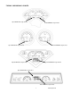
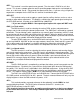
TYPICAL VHX DISPLAY LAYOUTS Speed/LCD1 Message Center Tach/LCD2 Message Center Speed/LCD1 Message Center Tach/LCD2 Message Center Speed/LCD1 Message Center Tach/LCD2 Message Center Speed/LCD1 Message Center Tach/LCD2 Message Center 3 MAN 650314:D
WARNING These are precision instruments and must be handled with care. Do not disassemble gauges. CARE AND CLEANING Never open the system or attempt to remove the needles as the calibration of the instrument system could be thrown off. All systems are calibrated and tested before they leave Dakota Digital. The clear lens on the front of the VHX system can be cleaned with a mild soap and water solution or common glass cleaners. Use a soft cloth such as a micro-fiber for wiping the lens clean.
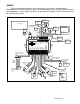
WIRING While the control box contains several connections, the wiring is straightforward. Depending on how many auxiliary functions you want displayed, not every terminal will be used in most applications. On the pages that follow, we describe the function of each terminal, what they do, and how to wire them.
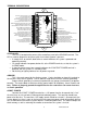
TERMINAL DESCRIPTIONS OIL OIL SND OIL + NIGHT DIMMING ADJUSTMENT GROUND OUTPUT NIGHT DIMMING ADJUSTMENT INPUT ADJ ADJ SND 2000 PPM SPEED SIGNAL OUTPUT VEHICLE SPEED SENSOR GROUND OUTPUT VEHICLE SPEED SENSOR SIGNAL INPUT VEHICLE SPEED SENSOR POWER OUTPUT RPM WARNING/SHIFT OUTPUT TACHOMETER INPUT +12 VOLT ACCESSORY POWER INPUT +12 VOLT CONSTANT POWER INPUT MAIN CHASSIS GROUND INPUT SW1 (-) SW2 (-) AUX.
ACC. POWER Connect the ACC. POWER terminal to accessory +12V power from the fuse panel or vehicle wiring harness. This terminal should have power when the key is on or in the ‘accessory’ position. In addition to turning on the display system, this is also where the voltmeter gauge senses the vehicle electrical system voltage. The accessory +12V supply source should be a fused 5 - 20 amp circuit, the system draws less than 1 amp, so sharing an existing accessory circuit will generally be fine.
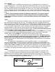
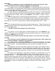
If you need the warn output to be “active high” or provide a +12V voltage to power something larger than 4 watt, a standard 12V relay can be used to accomplish this. 30 85 86 DO NOT CONNECT 87 SPD + This terminal is used to supply power to Dakota Digital speed sensor SEN-01-5. This supplies 5V DC to the sensor and should not be connected to anything else. Connect the RED wire from the SEN-01-5 to this terminal.
SPD – This terminal is used for speed sensor ground. The wire color is BLACK on a 3-wire sensor. This insures a proper ground as well as providing proper hook-up for a twisted pair of wires, or a solid state sensor. Only ground the speed sensor here. If you are using a single wire output from a computer for the VSS then this terminal should be left open. SPD OUT This terminal can be used to supply a speed signal to auxiliary devices such as a cruise control or radio volume adjustment.
WTR SND The water temperature sender included with this system must be used. Other senders will cause incorrect readings or damage to the control box. The supplied sensor, Dakota Digital SEN-04-5, is a 100-300ºF(40-150ºC) temp sensor. The sender mounts in the engine block, cylinder head, or intake manifold so that the end of the sensor is in the engine coolant flow. It has 1/8” NPT threads and the included adaptor bushings may be used to adapt it for various applications.
OIL – This is the ground reference used for three-wire pressure sensor. This will connect to the black wire as well as the bare silver shield wire from the Dakota Digital SEN-03-8. ***The bare wire is the shield wire, connect this wire to the OIL – along with the BLACK wire ***DO NOT connect this terminal to any other devices FUEL + This output is not typically used. It is a low current +12V supply for powering solid state fuel sensors.
CRUISE (-) The CRUISE terminal can be used as a “cruise engaged” indicator. The CRUISE input is activated by a ground signal from a compatible cruise control harness. Whenever the CRUISE input is grounded, the system will display a small green “cruise engage” indicator. WAIT (+) The WAIT terminal can be used as a “wait to start” or glow plug indicator. The WAIT input is activated by a 12 volt signal from the glow plugs.
BRAKE (-) The BRAKE terminal can be used as a brake system warning indicator. The BRAKE input is activated by a ground signal from the brake pressure switch on the master cylinder or from the parking brake set switch. Connect a wire from this terminal to the pressure switch on the master cylinder or consult a vehicle service manual to determine color and location of an existing wire. Whenever the BRAKE input is grounded, the system will display “check BRAKE” on the LCD 1 message display.
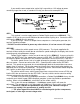
SETTING UP THE CONTROL BOX Below is the list of setup menus. You must have SW1 wired to enter setup, SW2 will be used in some menus as well; descriptions of each menu are below. Pay close attention to Setup menus and options as incorrect settings will cause faulty readings on the displays.
INFO Current software code Current pulse per mile cal value saved Exit setup menu VERSION SPEED CAL DONE Used to preset odometer reading Set ODOM To enter the setup mode, press and hold SW1 while turning the key/ACC power on. The display should light up and show SETUP on the speedometer/LCD1 and tachometer/LCD2 message displays. Release the switch and Setup SPEED should display on LCD1, this is the start of the setup menus. Press and release Switch 1 (SW1) to advance through the main menus.
Auto Cal (AUTO) This menu is used to calibrate the speed signal by driving a measured mile. Start this procedure with the vehicle stopped at the beginning of a known measured mile. Shut the car off, press and hold SW1 and turn the key on and start the car then release the switch to get into setup once the car is running. Then select the speed setup menus.
If “Bus” is selected for the sender type, the speed signal should be coming into the AUX I/O port through the use of a BIM module. The adjustment ratio ranges from 75 – 125% on this setting. It is assumed that the signal from the external device is the correct pulse rate, so there are only provisions for slight adjustment. The LCD1 message will light up and show “adjust spD xxx%”, XXX is adjustable from 75 – 125 and is the percentage the input is corrected by.
Press and hold SW1 while turning the key on. Release the switch. Press and release SW1 to get to the “TACH” setup menu. Press and hold the switch until “TACH ENGINE” is displayed to enter the tach setup menus, then release SW1. Now you can press and release the switch to scroll through the tach sub-menus, “ENGINE” “UPDATE” “WARN” “SIGNAL” “DONE”. When you get to the desired sub-menu, press and hold the switch to select it.
When “SIGNAL” is displayed, press and hold SW1 to enter the “SIGNAL” setup menu. Release SW1 and the current setting will be displayed. Press and release SW1 to toggle from “12V HIGH” to “5V LOW”. When the desired setting is displayed, press and hold SW1 until “DONE” is displayed. Release the switch to go on to the next sub-menu item. Exit tach setup (DONE) This will allow you to exit the tach setup and go on to the next setup menu.
*NOTE: Selecting Celsius units will only change the reading on the LCD message centers since the VHX needle sweeps are set for Imperial units. You will also need to enable the message in order to display it. When “sender” is displayed, press and hold SW1 until the message changes. Release SW1 and the current sensor selection will be displayed. Press and release SW1 to scroll through the sensor options “DD F” “DD C” “BUS F” “BUS C”.
OIL PRESSURE SETUP Dakota Digital only offers one pressure sensor for this system, SEN-03-8, 0-100 psi solid state sensor with 1/8” NPT threads. The Oil Pressure setup allows you to set up a low pressure warning point that will cause the message display to flash the oil pressure reading whenever the value is lower than the warning set point. There is also a test mode that will display the voltage from the sensor for trouble shooting assistance. Press and hold SW1 while turning the key on.
FUEL SETUP The control box can read seven common fuel level sender resistance values. If your sender is not shown in the table below, the system can be programmed to read a custom sender. The table below shows the seven pre-programmed senders and their respective empty and full resistance values.
Now, with the float in the empty position, press and release SW1. The message display will show “custom 33%” and “xxx OHMS”. Move the float to 1/3 full and then press and release SW1. The message display will show “custom 66%” and “xxx OHMS”. Move the float to 2/3 full and then press and release SW1. The message display will show “custom 99%” and “xxx OHMS”. Move the float to the full position and then press and release SW1. The new sender is now stored under the “CUSTOM CUSTOM” CUSTOM sender selection.
To set the level of brightness for night time driving: Press and hold SW1 while turning the key on. Release the switch. Press and release SW1 to get to the “LIGHTING” setup menu. Press and hold the switch until “LIGHTING DIM LEVEL” is displayed, then release SW1. Press and hold SW1 to enter brightness adjustment until a screen that says “dim level adjust --", then release the switch. A screen that reads “dim level adjust xx” should be displayed, where xx is the current level.
Secondary indicator setup (indicators) This menu will allow you to select where the indicators are displayed and if you want them shown in the face of the system, light only, or if you would like them also displayed in the LCD1 message center as well as the face so they are more visible in two locations.
INFORMATION MENU The information menu, “INFO” is used to display software code information should you have any troubles; this information can be useful for troubleshooting as well as verifying the current speedometer calibration value if using the normal speed input (SPD SND). To view the version of software your instrument system has, press and hold SW1 while turning the key on. Release the switch. Press and release SW1 to get to the “INFO” setup menu. Press and hold SW1 to enter menu.
LCD MESSAGE CONTRAST ADJUSTMENT MENU In some cases, mainly in systems where the message center would be mounted further apart from one another or at different angles in the dash, you may want to adjust the contrast of the LCD for better visibility. By default the contrast is set about midway and this setting should be acceptable for most applications, but you can change it for individual preference.
Speed/LCD1 message displays ODOMETER A MILES B MILES KM/H GEAR (with optional GSS-2000) SERVIC (when enabled) ENGINE BRAKE 4W DRV WAIT DESCRIPTION . Odometer reading (0-999,999) Trip A odometer reading (0-9999.9) Trip B odometer reading (0-9999.
TROUBLESHOOTING GUIDE This is a list of some problems and their solutions which may be encountered when installing your instrumentation system. If you cannot determine what the problem is or how to solve it, please call our technical assistance line (605) 332-6513 or email dakotasupport@dakotadigital.com. * A note on vehicle grounding * The most common cause of problems with electric gauges and other sensitive vehicle electronics is poor ground connections.
Symptom Possible Problem Solution ----------------------------------------------------------------------------------------------------------------------------------The tachometer reading The tachometer signal wire is Check the connections at both is incorrect. loose or broken. ends of the wire. The engine cylinder setting is Refer to the “Tach Setup” section incorrect. of the installation manual. The speedometer will not show a reading. The speed signal is not connected to the control box properly.
Symptom Possible Problem Solution ----------------------------------------------------------------------------------------------------------------------------------The fuel gauge reads backwards, incorrectly, or does not change. The control box may be set for the wrong type of fuel sender. The fuel sender may not be connected to the control box properly. The fuel sender may not be operating properly. The fuel sender may have a non-standard resistance range.
Symptom Possible Problem Solution ----------------------------------------------------------------------------------------------------------------------------------The Check Engine The Engine Control Module Connect a bulb with one wire to indicator stays on (ECM) needs to see the keyed power and the other to all of the time. load of a light connected to it. the CHECK ENG terminal. The Function switches do not operate properly. The push-button switches are not connected to the control box.
SERVICE AND REPAIR DAKOTA DIGITAL offers complete service and repair of its product line. In addition, technical consultation is available to help you work through any questions or problems you may be having installing one of our products. Please read through the Troubleshooting Guide. There, you will find the solution to most problems. Should you ever need to send the unit back for repairs, please call our technical support line, (605) 332-6513, to request a Return Merchandise Authorization number.
MAN 650314:D