
Service manual
MAN 650314:D
10
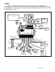
WTR SND
The water temperature sender included with this system must be used. Other
senders will cause incorrect readings or damage to the control box.
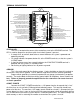
The supplied sensor, Dakota Digital SEN-04-5, is a 100-300ºF(40-150ºC) temp sensor.
The sender mounts in the engine block, cylinder head, or intake manifold so that the end of the
sensor is in the engine coolant flow. It has 1/8” NPT threads and the included adaptor bushings
may be used to adapt it for various applications.
To avoid mounting an additional temperature sender on the engine, a Dakota Digital BIM-
01-1 may also be used with most 1996 or newer OBDII compliant computer systems to provide
an engine temperature reading. When using the BIM-01-1, select “BUS F” or “BUS C” for the
sender type.
The water temp sensor has two wires coming from the harness. The BLUE or RED wire
will connect to the WTR SND terminal, the BROWN or BLACK wire will connect to the WTR –.
Due to the construction of the sensor, readings at lower temperatures below 100 ºF may
be inaccurate. The sensor is designed to be accurate from approximately 100 ºF - 300 ºF.
WTR –
This is the ground reference used for 2-wire water temp sensors. This will connect to the
BROWN or BLACK wire from the Dakota Digital SEN-04-5. The BLUE or RED wire will connect
to the WTR SND terminal.
***DO NOT connect this terminal to any other devices
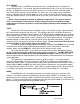
OIL +
This terminal is used to supply power to Dakota Digital pressure sensor SEN-03-8. This
supplies 5V DC to the sensor and should not be connected to anything else. Connect the RED
wire from the SEN-03-8 to this terminal.
***DO NOT use this terminal to power any other devices; it is a low current +5V output.
OIL SND
The oil pressure sender included with this system must be used. Other senders will
cause incorrect readings or damage to the control box.
The supplied sensor, Dakota Digital SEN-03-8, is a 0-100 psi solid state pressure sensor.
The sender can mount on the engine block or in an oil pressure line off of the block. The sender
has 1/8” NPT threads. The included adaptor bushings may be used to adapt it for various
applications.
The oil pressure sensor has three wires coming from the harness, plus one bare shield
wire. The WHITE wire will connect to the OIL SND terminal, the RED to OIL + (5V DC), and the
BLACK and bare shield wire to OIL –. Do not route the oil sender wire alongside a spark plug
wire or other high current or high voltage wires. Doing so can cause incorrect or erratic gauge
readings.
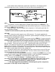
If the oil pressure drops below an adjustable warning point, the reading will flash as a low
oil pressure warning. The default warning point is 10 psi. If the oil display shows in a LCD
message screen as “ - - ”, this indicates that the control box is sensing an open circuit, a short to
ground, or out-of-range error from the sender or sender wire. If the oil display shows “EEE” this
indicates that the control box is sensing a short to power or out-of-range error from the sender. If
either indication remains on the display, inspect the sender wire for damage, check the routing of
the sender wire, check the sending unit grounding, and check that the correct sending unit is
connected.