
Service manual

MAN 650314:D
4
WARNING
These are precision instruments and must be handled with care. Do not disassemble gauges.
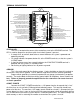
CARE AND CLEANING
Never open the system or attempt to remove the needles as the calibration of the
instrument system could be thrown off. All systems are calibrated and tested before they
leave Dakota Digital.
The clear lens on the front of the VHX system can be cleaned with a mild soap and water
solution or common glass cleaners. Use a soft cloth such as a micro-fiber for wiping the lens
clean.
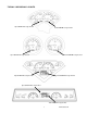
MOUNTING SYSTEMS
Most VHX systems and kits will come with a separate instruction sheet with mounting
details. Follow this sheet for mounting the actual display system in the dash, and then refer to
this manual for wiring and operation instructions.
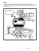
CONTROL BOX MOUNTING
Once the display panel is in place, mount the control box within reach of the supplied
networking cable (approximately three (3) feet). If a longer cable is required, replacement CAT5
cables are available online as well as your local electronics stores. Choose a mounting location
that will allow you access to wire all of the inputs on either side of the control box. Double sided
tape, hook and loop fasteners or screws in the two tabs on the case work fine for securing the
control box under the dash.
When selecting a mounting location, avoid placing the control module next to, or
just opposite of the firewall from, ignition components, i.e.: Ignition coil, HEI, etc. Ignition
components can emit tremendous amounts of electrical noise, affecting the operation of
electrical components which can cause erratic operation.
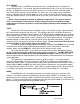
***If you are purchasing a longer network cable to connect the display system to the
control box please make sure to get a CAT 5, CAT5E, or CAT6 “patch cable” and NOT a
“cross over” cable. Replacement cable should be seven feet or less.