
Service manual

MAN 650314:D
8
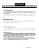
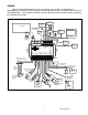
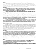
If you need the warn output to be “active high” or provide a +12V voltage to power
something larger than 4 watt, a standard 12V relay can be used to accomplish this.
86
87
85
30
DO NOT CONNECT
SPD +
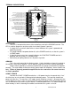
This terminal is used to supply power to Dakota Digital speed sensor SEN-01-5. This
supplies 5V DC to the sensor and should not be connected to anything else. Connect the RED
wire from the SEN-01-5 to this terminal.
If you are using a 1-wire VSS output from a computer or a 2-wire pulse generator, this
terminal should be left open.
***DO NOT use this terminal to power any other devices; it is a low current +5V output.
SPD SND
This is where the vehicle speed sensor (VSS) connects. The signal supplied to this
terminal will be used by the control box to calculate the speed reading on the display and also for
calculating and saving odometer mileage.
Dakota Digital supplies a 3-wire sensor for most of its kits; SEN-01-5. If you are using this
sensor, the WHITE wire is the speed signal; connect to SPD SND. The RED and BLACK wires in
the cable are power and ground (5V DC) and their connection is discussed in SPD + and SPD -.
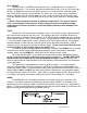
For 2-wire speed sensors such as a cable driven pulse generator, the polarity of the wires
does not matter. Connect one wire to the SPD – (Ground) and the other to the SPD SND
terminal. The speed sensor ground wire should be brought back to the control box to ensure a
proper signal is received. Twisting the ground and signal wires around each other provides an
additional level of interference protection. The speed signal wire should not be routed alongside
tach, ignition, or other high current or high voltage wires.
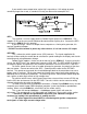
For vehicles which have a vehicle speed signal from a transmission sensor or ECM, tap
into the VSS wire and connect it to the SPD SND. Consult a vehicle service manual or wiring
diagram to determine wire color and location.
To avoid having to locate a compatible connection, a Dakota Digital BIM-01-1 may also be
used with most 1996 or newer OBDII compliant computer systems to provide a speedometer
reading. When using the BIM-01-1, select “BUS” for the sender setting.
This system can accept 4,000 ppm – 128,000 ppm speed signals with room for
adjustment. The speedometer is fully adjustable and calibration is discussed in a later section.
***Failure to calibrate the speedometer may cause your odometer mileage to
increase very rapidly if the speedometer is reading too fast.
*** The speed signal wire should NOT be routed alongside ignition components,
tach signal, or other high current/voltage wires.