
- Dakota Digital, Inc. Clock User's Manual


1
MAN #650360
Operating Manual for
Clock / Auxiliary Displays for VHX systems
The VHX auxiliary display module is designed to work with a Dakota Digital VHX system and will not function properly
on its own. With this module, an additional display area is added to your current system to provide more functionality.
This module can be used as a simple clock display or it can display data from any BIM module attached to the system
as well as several gauge values from the control box sensors.
Most versions of this module come with at least one switch in the face to allow the display to change between various
screens. Some versions may also contain two additional switches in the face which can be used as the SW1 and SW2
for the VHX control box with the use of the switch harness provided with it.
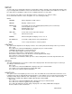
CONNECTION:
The auxiliary display has a connector on the rear that will accept a normal CAT 5, CAT 5E, or CAT 6 patch cable.
This can be used to connect the module to any available port on the VHX control box (same locations the main
VHX gauges plug into).
ACC. POWER
CONST. POWER
GROUND
TACH
WARN
SPD +
SPD SND
SPD -
SPD OUT
SW2 (-)
SW1 (-)
ADJ SND
ADJ -
WTR SND
WTR -
OIL +
OIL SND
OIL -
FUEL +
FUEL SND
FUEL -
WAIT (+)
CRUISE (-)
GEAR (1 WIRE)
4x4 (-)
RIGHT (+)
LEFT (+)
HIGH (+)
BRAKE (-)
CHECK ENG (-)
VHX
CONTROL BOX
CABLE AUX.
I/O
DISPLAY
www.dakotadigital.com
techsupport@dakotadigital.com
605-332-6513
DIM (+)
ORANGE
GREEN
Used for displays
with 3 switches
Connection for all
auxiliary displays
Use any open jack
Auxiliary Display module
VHX
control
box
OR
SWITCH HARNESS:
Some auxiliary modules will come with the
pictured switch harness to allow additional
switches in the clock face to function as switch
1 and 2 for the main VHX system.
Auxiliary modules with 3 switches on front:
Connect the orange wire to SW1(-) terminal on VHX control box. Right switch will be SW1 (speed display).
Connect the green wire to SW2(-) terminal on VHX control box. Left switch will be SW2 (tach display).
Leave blue wire unconnected. Center switch will be SW3 (clock display)
Auxiliary modules with no switches on front:
If the module has no switches, connect an external switch from the blue wire of the harness to ground to allow
switch operations for the clock display. The orange and green wires would be left unconnected in this case.
ORANGE (switch 1)
GREEN (switch 2)
BLUE (switch 3)