OPERATION MANUAL DAKOTA ULTRASONICS CMX Material & Coating Thickness Gauge P/N P-170-0002 Rev 1.
CHAPTER ONE INTRODUCTION .......................................................................1 CHAPTER TWO QUICK STARTUP GUIDE ........................................................2 CHAPTER THREE KEYBOARD, MENU, & CONNECTOR REFERENCE.......22 CHAPTER FOUR PRINCIPALS OF ULTRASONIC MEASUREMENT .............30 CHAPTER FIVE SELECTING THE MEASUREMENT MODE ..........................35 CHAPTER SIX MAKING MEASUREMENTS .....................................................
CHAPTER ONE INTRODUCTION The Dakota Ultrasonics model CMX is an ultrasonic thickness gauge that measures with extreme versatility. It has the ability to simultaneously measure coatings and material thicknesses while maintaining the ability to still locate pits, flaws and defects in the material. Based on the same operating principles as SONAR, the CMX is capable of measuring the thickness of various materials with accuracy as high as ± 0.001 inches, or ± 0.01 millimeters.
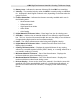
CHAPTER TWO QUICK STARTUP GUIDE Turn the CMX on and off using the switch located on the bottom right corner of the keypad. When CMX is initially turned on, a flash logo and blinking lights will be displayed, followed by attempting to identify the transducer(probe) currently plugged into the gauge. The CMX is equipped with an “Auto Probe Recognition” feature that attempts to identify special transducers with this built in feature.
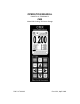
CMX High Performance Material & Coating Thickness Gauge B. Battery Icon – Indicates the amount of battery life the CMX has remaining. C. Velocity – The material velocity value the CMX is currently using or calibrated for. Displayed in both English or Metric units, depending on the what units the gauge is set for. D. Feature Status Bar – Indicates the features currently enabled and in use in the following order: • Measurement Mode • Differential Mode • High Speed Scan Mode • Alarm Mode • Gain Setting E.
Dakota Ultrasonics 2.2 Auto Probe Recognition When the CMX is initially powered up, the gauge will automatically check to see if the transducer plugged into the gauge can be recognized. The steps that follow assume the CMX recognized the probe type: Probe Automatically Recognized 1) Press the OK key once to use the identified probe, or ESC to display a list of optional transducers. Note: if the CMX recognizes a specific transducer, the user should always select OK to use the identified probe.
CMX High Performance Material & Coating Thickness Gauge 3) Press the UP and DOWN arrow keys to toggle the coating option on/off. 4) Wipe all couplant from the transducer face and advance to the Probe Zero & Calibration section outlined below. 2.3 Selecting the Transducer Type If the CMX does not identify a specific transducer type on initial power up, the user will be required to select a type from a predefined list of types by diameter and frequency.
Dakota Ultrasonics Selecting the Transducer Type 1) Press the OK or ESC keys to display the factory list of transducer types (by diameter and frequency). 2) Press the UP and DOWN arrow keys to scroll through the transducer list until the appropriate type is highlighted.
CMX High Performance Material & Coating Thickness Gauge 3) Press the ENTER key to select the transducer type and display overwrite existing probe screen. 4) Press the OK key to overwrite the existing probe type with the newly selected probe type. The zero probe screen will be displayed. Proceed to the zero p robe section that follows. 2.4 Probe Zero & Calibration The next steps are to perform a probe zero and calibrate the CMX to the material and transducer being used.
Dakota Ultrasonics Performing an Auto Probe Zero (Off Block) Coating Probe Identified Coating Probe Not Identified 1) Be sure all couplant has been removed from the face of the transducer. 2) Press the OK key to perform the automatic probe zero, or ESC key to cancel the zero operation. Coating Probe Identified Coating Probe Not Identified 3) The screens illustrated above will be briefly displayed followed by the main measurement screen. The CMX is ready to be calibrated.
CMX High Performance Material & Coating Thickness Gauge Performing a Manual Probe Zero (On Block) Note: When the zero probe option is set to manual, the probe zero disk (battery cap) located o n the top of the gauge, will be used as a zero standard and the warning screen illustrated above will be displayed. 1) Press the OK or ESC keys to enter the main measurement screen and begin the manual zero process.
Dakota Ultrasonics Coating Probe Identified Coating Probe Not Identified 5) Press the ENTER key to display the confirmation screen. 6) If a coating transducer was identified use the UP and DOWN arrow keys to toggle coating on/off. 7) Press the OK key to complete the probe zero function, or ESC key to cancel the probe zero function. 8) Remove the transducer from the probe zero disk, and proceed to the calibration section.
CMX High Performance Material & Coating Thickness Gauge Using a Known Thickness Note: Be sure that the probe zero procedure has been performed prior to performing this calibration procedure. 1) Physically measure an exact sample of the material or a location directly on the material to be measured using a set of calipers or a digital micrometer. 2) Apply a drop of couplant on the transducer and place the transducer in steady contact with the sample or actual test material.
Dakota Ultrasonics 4) Press the ENTER key to display the Digits Edit Box. 5) Press the UP and DOWN arrow keys to scroll the highlighted value. 6) Press the LEFT and RIGHT arrow keys to scroll the digit locations. 7) Repeat steps 5 & 6 until the known thickness value is correctly displayed. 8) Press the OK key to calculate the velocity and return to the menu screen, or ESC to cancel the one point calibration. 9) Finally, press the MEAS key to return to the measurement screen and begin taking readings.
CMX High Performance Material & Coating Thickness Gauge Performing a Coating Zero 1) Press the MULTI MODE key once to activate the measurement mode options. 2) Use the UP and DOWN arrow keys to scroll through the sub menu items until Coating Only (CT) mode is highlighted. 3) Press the ENTER key to select the measurement mode and return to the measurement screen.
Dakota Ultrasonics 6) Use the UP and DOWN arrow keys to scroll through the sub menu items until ZERO COATING is highlighted. 7) Press the ENTER key to display the confirmation screen. 8) Press the OK key to zero the coating and retur n to the PRB menu, or ESC to cancel the coating zero process. 9) Press the MULTI MODE key once to activate the measurement mode options. 10) Use the UP and DOWN arrow keys to scroll through the sub menu items until Coating On (PECT) is highlighted.
CMX High Performance Material & Coating Thickness Gauge quick start section only the 1pt option PECT (pulse-echo coating) mode will be covered. Refer to the calibration section of the manual for a complete explanation on the coating calibration options.
Dakota Ultrasonics 17) Repeat steps 4 & 5 until the velocity number is correctly displayed. 18) Press the OK key to set the coating velocity and return to the menu screen, or ESC to cancel entering the coating velocity. 19) Finally, press the MEAS key to return to the measurement screen and begin taking readings.
CMX High Performance Material & Coating Thickness Gauge Important Note: In PECT (pulse-echo coating) mode, the coating sample must be coupled to metal in order to calibrate successfully. Simply place a drop of couplant on a piece of metal, lay the coating sample over the couplant on the metal and proceed to step 2. 2) Apply a drop of couplant on the transducer and place the transducer in steady contact with the coating (on metal) sample or actual test material.
Dakota Ultrasonics 8) Press the OK key to calculate the coating velocity and return to the menu screen, or ESC to cancel the one point calibration. 9) Finally, press the MEAS key to return to the measurement screen and begin taking readings. Note: CHECK YOUR CALIBRATION! Place the transducer back on the calibration point. The coating thickness reading should now match the known coating thickness sample. If the thickness is not correct, repeat the steps above. 2.7 Measure The CMX is now ready to measure.
CMX High Performance Material & Coating Thickness Gauge 2) Use the UP and DOWN arrow keys to scroll through the sub menu items until VIEW is highlighted. 3) Use the LEFT and RIGHT arrow keys to scroll the view options. 4) Once the view is displayed, press the MEAS key to return to measurement mode. DIGITS: Displays the digital thickness value using a large font size. This view is useful when the CMX is being used as a basic thickness gauge.
Dakota Ultrasonics 1) Press the MENU key once to activate the menu items tab. Press the MENU key multiple times to tab right and the ESC key multiple times to tab left until the DISP menu is highlighted and displaying the submenu items. 2) Use the UP and DOWN arrow keys to scroll through the sub menu items until B-START or B-DEPTH is highlighted. 3) Use the LEFT or RIGHT arrow keys to increase/decrease the start or depth values in coarse increments/decrements.
CMX High Performance Material & Coating Thickness Gauge 5) Repeat steps 3 & 4 until the B-START or B-DEPTH value is correctly displayed. 6) Press the OK key to set the B-START or B-DEPTH value and return to the DISP menu, or ESC to cancel entering the B-START or B-DEPTH value. Note: the adjusted value will appear next to the B-START or B-DEPTH menu labels. 7) Finally, press the MEAS key to return to the measurement screen and begin taking readings.
CHAPTER THREE KEYBOARD, MENU, & CONNECTOR REFERENCE 3.1 Menu Key (Operation & Sub Menus) The Menu key activates the primary menu structure containing 8 menu tab groups. These tab groups then contain sub menu items, or functions. The sub menu items have been organized in tab groups according to how closely they are related to the individual tab group names. Let’s first get familiar with how to move around in these tabs before continuing on to the sub menu functions.
CMX High Performance Material & Coating Thickness Gauge Activating and Getting Around in the Menu Items 1) Press the MENU key once to activate the menu items tab. Press the MENU key multiple times to tab right, and the ESC key multiple times to tab left until the desired tab group is highlighted and displaying the submenu items. The tab groups are illustrated above (A).
Dakota Ultrasonics 3.2 Probe – Menu ZERO PROBE: The CMX is zeroed in much the same way that a mechanical micrometer is zeroed. If the CMX is not zeroed correctly, all of the measurements made using the CMX may be in error by some fixed value. The CMX is equipped with an optional automatic or manual zero feature. Refer to the section on page 42, for an explanation of this important procedure.
CMX High Performance Material & Coating Thickness Gauge COATING 1PT: Performs a single point coating calibration. This option allows the user to automatically calculate the velocity by measuring a known coating sample thickness. Refer to page 76 for further info. COATING 2PT: Performs a two-point coating calibration. This option allows the user to automatically calculate the velocity by entering a second known coating sample thickness. Refer to page 76 for further info.
Dakota Ultrasonics 3.6 SETUP – Menu OPEN: Displays a list of factory and user defined setups currently stored in memory. These setups can be recalled and used at any time. Refer to page 86 for further info. SAVE: Provides the user with the ability to save a custom setup that has been modified or created by the user. Refer to page 88 for further info. DELETE: Provides the user with the ability to delete specific setups previously save in memory. Refer to page 92 for further info.
CMX High Performance Material & Coating Thickness Gauge 3.8 XFER (transfer) – Menu BACKUP SETUPS: Enables the user the ability to backup the setups currently stored in the CMX to a PC via RS232 port. Refer the help section of the CMX DakView software for a complete electronic manual. RESTORE SETUPS: Enables the user the ability to restore the setups currently saved on a PC to an CMX via RS232 port. Refer the help section of the CMX DakView software for a complete electronic manual.
Dakota Ultrasonics 3.13 Arrow Keys The Arrow Keys are used to navigate through the menus, increase/decrease values, and toggle specific function keys. 3.14 ENTER key The ENTER key is used in the overall menu selection process to activate list and edit boxes. 3.15 MULTI MODE Key The MULTI MODE key opens a measurement mode screen listing all the modes that are available to the transducer specifically selected.
CMX High Performance Material & Coating Thickness Gauge 3.17 Top & Bottom End Caps The top & bottom end panels are where all connections are made to the CMX. The diagram above shows the layout and description of the connectors: Transducer Connectors Refer to Diagram: The transducer connectors, and battery cover/probe zero disk are located on the CMX’s top e nd cap. The transducer connectors are of type Lemo “00”. Note: There is no polarity associated with connecting the transducer to the CMX.
CHAPTER FOUR PRINCIPALS OF ULTRASONIC MEASUREMENT 4.1 Time versus thickness relationship Ultrasonic thickness measurements depend on measuring the length of time it takes for sound to travel through the material being tested. The ratio of the thickness versus the time is known as the sound velocity. In order to make accurate measurements, a sound ve locity must be determined and entered into the instrument. The accuracy of a thickness measurement therefore depends on having a consistent sound velocity.
CMX High Performance Material & Coating Thickness Gauge through air efficiently. By using a liquid couplant between the transducer and test piece the amount of ultrasound entering the test piece is much greater. 4.5 Temperature Temperature has an effect on sound velocity. The higher the temperature, the slower sound travels in a material. High temperatures can also damage transducers and present a problem for various liquid couplants.
Dakota Ultrasonics V-Path Correction Dual element delay line transducers have two piezoelectric elements mounted at an angle on one end of the delay line. One element is used for transmitting sound, while the other element only receives sound. The two elements and their delay lines are packaged in a single housing but acoustically isolated from each other with a sound barrier. This allows the transducer the ability to achieve very high sensitivity for detecting small defects.
CMX High Performance Material & Coating Thickness Gauge Dual Element Transducer in Echo to Echo mode Echo-Echo Verify Mode – Thru-Verify (E-EV) The echo-echo verify mode measures between 3 reflections. Similar to E-E mode, this technique is commonly used to eliminate errors from surface coatings and also to make measurements in multiple layered materials.
Dakota Ultrasonics Pulse-Echo Temperature Compensated Mode – Temp Comp (PETP) This is a custom mode that combines pulse-echo and electronic zero techniques to automatically adjust for temperature changes in the transducer as a result of an increasing/decreasing temperature gradient in the test material. Note: rough surface conditions can have an effect on the overall accuracy in this mode.
CHAPTER FIVE SELECTING THE MEASUREMENT MODE 5.1 The setup library The CMX contains 64 user configurable preset locations to store custom setups for easy recall. These setups can be optimized for the user’s specific application needs and can also be stored on a PC and transferred bi-directionally using Dakota’s PC interface software included with the instrument. The setups supplied with the instrument cover some of the more typical applications commonly used with this type of instrument.
Dakota Ultrasonics Thru Paint & Coatings Often times users will be faced with applications where the material will be coated with paint or some other type of epoxy material. Since the velocity of the coating is approximately 2.5 times slower than that of steel, pulse-echo mode will induce error if the coating or paint is not completely removed.
CMX High Performance Material & Coating Thickness Gauge Restricted access Measuring materials with extreme curvatures or restricted access, higher frequencies with smaller diameters should be considered. The smallest diameter uses 3/16” crystals with a contact area of .250”. Custom transducers are available on request. 5.
CHAPTER SIX MAKING MEASUREMENTS The steps involved in making measurements are detailed in this section. The following sections outline how to setup and prepare your CMX for field use. An automatic or manual zero must always be performed. The auto zero is an off block electronic zero that does not require a zero reference block. This will most always be the zero option of choice, as it makes the zeroing process very easy and convenient to perform.
CMX High Performance Material & Coating Thickness Gauge In this first example the transducer was automatically identified: Probe Automatically Recognized 1) Press the OK key once to use the identified probe, or ESC to display a list of optional transducers. Note: if the CMX recognizes a specific transducer, the user should always select OK to use the identified probe.
Dakota Ultrasonics 3) Press the UP and DOWN arrow keys to toggle the coating option on/off. 4) Wipe all couplant from the transducer face and proceed to the Probe Zero section that follows . In this second example the transducer was not identified and will force the user to select the transducer type from a predefined list of transducers: Selecting the Transducer Type 5) Press the OK or ESC keys to display the factory list of transducer types (by diameter and frequency).
CMX High Performance Material & Coating Thickness Gauge 6) Press the UP and DOWN arrow keys to scroll through the transducer list until the appropriate type is highlighted. 7) Press the ENTER key to select the transducer type and display overwrite existing probe screen. 8) Press the OK key to overwrite the existing probe type with the newly selected probe type. The zero probe screen will be displayed. Proceed to the zero probe section that follows.
Dakota Ultrasonics 6.2 Probe zero The next step is to perform a probe zero. The zero function is a very important and necessary function that must be done prior to calibration. It should be done on a regular basis. In fact, the CMX has been programmed to force this issue at regular intervals during operation if it hasn’t been done. If the CMX is not zeroed correctly, all the measurements taken may be in error by some fixed value.
CMX High Performance Material & Coating Thickness Gauge 2) Press the OK key to perform the automatic probe zero, or ESC key to cancel the zero operation. Coating Probe Identified Coating Probe Not Identified 3) The screens illustrated above will be briefly displayed followed by the main measurement screen. The CMX is ready to be calibrated.
Dakota Ultrasonics Note: When the zero probe option is set to manual, the probe zero disk (battery cap) located on the top of the gauge will be used as a zero standard and the warning screen illustrated above will be displayed. 1) Press the OK or ESC keys to enter the main measurement screen and begin the manual zero process. 2) Apply a drop of couplant on the transducer and place the transducer in steady contact with the probe zero disk and obtain a steady reading.
CMX High Performance Material & Coating Thickness Gauge 7) Press the OK key to complete the probe zero function, or ESC key to cancel the probe zero function. 8) Remove the transducer from the probe zero disk, and proceed to the calibration section. Note: The value that is displayed will change depending on the current velocity setting in the CMX. Disregard the number that is displayed. It is not important.
Dakota Ultrasonics 1) Press the MENU key once to activate the menu items tab. Press the MENU key multiple times to tab right and the ESC key multiple times to tab left until the CAL menu is highlighted and displaying the submenu items. 2) Use the UP and DOWN arrow keys to scroll through the sub menu items until VELOCITY is highlighted. 3) Press the ENTER key to display the Digits Edit Box. 4) Press the UP and DOWN arrow keys to scroll the highlighted value.
CMX High Performance Material & Coating Thickness Gauge 7) Press the OK key to set the velocity and return to the menu screen, or ESC to cancel entering the velocity. 8) Finally, press the MEAS key to return to the measurement screen and begin taking readings.
Dakota Ultrasonics Known Thickness Sometimes the sound velocity of a material is unknown. In this case a sample with one or two known thicknesses can be used to determine the sound velocity. As previously discussed, the CMX has a one or two point calibration option. The one point calibration option is most suited for linearity over large ranges, as noted above. The user should also consider calibrating on high side of the intended measurement range, when using the one point option, minimize overall error.
CMX High Performance Material & Coating Thickness Gauge ESC key multiple times to tab left until the CAL menu is highlighted and displaying the submenu items. 3) Use the UP and DOWN arrow keys to scroll through the sub menu items until MATL 1PT is highlighted. 4) Press the ENTER key to display the Digits Edit Box. 5) Press the UP and DOWN arrow keys to scroll the highlighted value. 6) Press the LEFT and RIGHT arrow keys to scroll the digit locations.
Dakota Ultrasonics the job. For example, if the measurement range was .080” (2.03mm) to .250” (6.35mm), the user would perform a one point calibration on a known thickness sample close to .250” (6.35mm), followed by a two point calibration close to .080” (2.03mm). When a two point calibration is performed, the CMX calculates the zero and the velocity.
CMX High Performance Material & Coating Thickness Gauge 4) Press the ENTER key to display the Digits Edit Box. 5) Press the UP and DOWN arrow keys to scroll the highlighted value. 6) Press the LEFT and RIGHT arrow keys to scroll the digit locations. 7) Repeat steps 5 & 6 until the known thickness value is correctly displayed. 8) Press the OK key to calculate the velocity and return to the menu screen, or ESC to cancel the one point calibration.
Dakota Ultrasonics being tested. Use these values only if a close approximation is acceptable. Follow the steps below to select a basic material type: Selecting a Basic Material Type 1) Press the MENU key once to activate the menu items tab. Press the MENU key multiple times to tab right and the ESC key multiple times to tab left until the CAL menu is highlighted and displaying the submenu items. 2) Use the UP and DOWN arrow keys to scroll through the sub menu items until MAT is highlighted.
CMX High Performance Material & Coating Thickness Gauge 4) Press the UP and DOWN arrow keys to scroll through the material list until the appropriate material is highlighted. 5) Press the ENTER key to overwrite the material type and display the menu items with the new material type selected. 6) Finally, press the MEAS key to return to the measurement screen and begin taking readings.
CHAPTER SEVEN USING THE DIGITS & B-SCAN DISPLAYS A key feature of the CMX is the ability to toggle between two different display options, Digits and B-Scan. The Digits view provides the user with a large digital readout of the thickness. Both views also include a scan bar features that uses a bar graph to indicate thickness.
CMX High Performance Material & Coating Thickness Gauge 7.1 Display Views DIGITS VIEW DIGITS The Digits view is a basic digital thickness gauge look and feel. The larger digits make it much easier for the operator to monitor the thickness readings. The Scan Bar has also been added to the Digits view to provide the user with yet another visual tool for easily monitoring changes in thickness readings due to internal flaws or defects. The following is a list of the viewable features on the display: A.
Dakota Ultrasonics E. F. G. H. I. J. • Alarm Mode • Gain Setting Digital Material Thickness Value – Extra large font size for viewing ease. Scan Bar – Another view of material thickness in a deflection style horizontal bar. This is another visual tool that would enable the user the ability to see thickness changes during high speed scans from flaws and pits. Units – The current measurement units being used (English, Metric).
CMX High Performance Material & Coating Thickness Gauge the user would see is a black screen from 0.00” – 1.00” with no view of the bottom contour at 1.75”. The following is a list of the viewable features on the display: A. Repeatability/Stability Indicator – This indicator should be commonly used in conjunction with the digital thickness values displayed.
Dakota Ultrasonics 7.2 Activating B-Scan View To use the B-Scan feature it must be enabled in the display menu. The following steps will help you do just that: Enabling the B-Scan Feature 1) Press the MENU key once to activate the menu items tab. Press the MENU key multiple times to tab right, and the ESC key multiple times to tab left, until the DISP menu is highlighted and displaying the submenu items. 2) Use the UP and DOWN arrow keys to scroll through the sub menu items until VIEW is highlighted.
CMX High Performance Material & Coating Thickness Gauge 7.3 Adjusting the B-Scan Start (B-START) & Depth (B-DEPTH) In order to use the B-Scan and Scan Bar features of the CMX effectively, the starting depth and overall depth must be setup correctly. This can be adjusted using the BSTART and the B-DEPTH features of the CMX. The B-START refers to the starting depth or thickness value displayed. Example: If you want your B-Scan or Scan Bar to start at a zero thickness value, then B-START must be set to 0.
Dakota Ultrasonics Adjusting the Starting Depth (B-START) 1) Press the MENU key once to activate the menu items tab. Press the MENU key multiple times to tab right, and the ESC key multiple times to tab left, until the DISP menu is highlighted and displaying the submenu items. 2) Use the UP and DOWN arrow keys to scroll through the sub menu items until B-START is highlighted. 3) Press the LEFT and RIGHT arrow keys to scroll the value. When the correct B-Start value is being displayed, proceed to step 8.
CMX High Performance Material & Coating Thickness Gauge 5) Press the UP and DOWN arrow keys to scroll the highlighted value. 6) Press the LEFT and RIGHT arrow keys to scroll the digit locations. 7) Repeat steps 5 & 6 until the B-Start value is correctly displayed. 8) Press the OK key to set the B-Start value and return to the menu screen, or ESC to cancel entering the B-Start. 9) Finally, press the MEAS key to return to the measurement screen and begin taking readings.
Dakota Ultrasonics 2) Use the UP and DOWN arrow keys to scroll through the sub menu items until B-DEPTH is highlighted. 3) Press the LEFT and RIGHT arrow keys to scroll the value. When the correct width is being displayed, proceed to step 8. 4) Alternatively , press the ENTER key to display the Digits Edit Box. 5) Press the UP and DOWN arrow keys to scroll the highlighted value. 6) Press the LEFT and RIGHT arrow keys to scroll the digit locations.
CMX High Performance Material & Coating Thickness Gauge 7.4 Gain The gain, or amplification of the return echoes, can be adjusted in the CMX to accommodate a variety of applications. The setting of the gain is crucial in order to obtain valid readings during the measurement process. Too much gain may result in erroneous measurements, by detecting on noise rather than the actual material back wall itself. Not enough gain may result in intermittent detection.
Dakota Ultrasonics Adjusting the Gain 1) Press the MENU key once to activate the menu items tab. Press the MENU key multiple times to tab right, and the ESC key multiple times to tab left, until the TUNE menu is highlighted and displaying the submenu items. 2) Use the UP and DOWN arrow keys to scroll through the sub menu items until GAIN is highlighted. 3) Press the LEFT and RIGHT arrow keys to scroll the value.
CHAPTER EIGHT THRU PAINT MEASUREMENT TECHNIQUE 8.1 Introduction to Thru Paint Measurement The principle behind thru paint measurement is by measuring the time between two backwall echoes returning from the test material. Since both of these backwall echoes travel the same path through the paint or coating, the thickness of the coating is subtracted out of the measurement so that only the actual material thickness can be measured.
CHAPTER NINE PULSE-ECHO COATING & COATING TECHNIQUES 9.1 Introduction to Pulse-Echo Coating Measurement (PECT) In the previous sections we’ve discussed the need for detecting pits and flaws (pulseecho) in materials, along with the requirement to measure through and eliminate errors caused by coated materials (echo-echo). Until now, both modes were needed in order accomplish both tasks.
CMX High Performance Material & Coating Thickness Gauge 3) From the tabbed menus under TUNE, MEASURE MODE. The steps that follow will demonstrate all three methods in the order listed above: Probe Automatically Recognized (PECT only) 1) Press the OK key once to use the identified probe, or ESC to display a list of optional transducers. Note: if the CMX recognizes a specific transducer, the user should always select OK to use the identified probe.
Dakota Ultrasonics 3) Press the UP and DOWN arrow keys to toggle the coating option on/off. Multi Mode Key Pressed (PECT & CT) Applied to Metals Not Applied to Metals 1) Press the MULTI MODE key located on bottom left of the keypad to display the MEASURE MODE options menu. 2) Press the UP and DOWN arrow keys to highlight the COATING ON (PECT) or COATING ONLY (CT) menu option.
CMX High Performance Material & Coating Thickness Gauge 3) Press the ENTER key to enable the coating option, or ESC to cancel changing the measure mode, and return to the main measurement screen. Measure Mode (Tabbed Menus) – (PECT & CT) Applied to Metals Not Applied to Metals 1) Press the MENU key once to activate the menu items tab. Press the MENU key multiple times to tab right, and the ESC key multiple times to tab left, until the TUNE menu is highlighted and displaying the submenu items.
Dakota Ultrasonics 9.3 Zero Coating In order to account for very slight electronic differences in transducers of the same type, frequenc y, and diameter, the CMX DL+ has been equipped with a “zero coating” feature. This enables the CMX DL+ to obtain very accurate readings on coatings, eliminating potential errors incurred from slight differences in the manufacturing processes.
CMX High Performance Material & Coating Thickness Gauge 5) Press the MENU key once to activate the menu items tab. Press the MENU key multiple times to tab right and the ESC key multiple times to tab left until the PRB menu is highlighted and displaying the submenu items. 6) Use the UP and DOWN arrow keys to scroll through the sub menu items until ZERO COATING is highlighted. 7) Press the ENTER key to display the confirmation screen.
Dakota Ultrasonics 9.4 Coating Calibration (PECT) Known Velocity If the coating velocity is known, the user may wish to simply enter the velocity number into the CMX, rather than have the CMX calculate the velocity value using a known thickness on a coating sample(s). The steps for entering the velocity are outlined below: Using a Known Material Velocity 1) Press the MENU key once to activate the menu items tab.
CMX High Performance Material & Coating Thickness Gauge 3) Press the ENTER key to display the Digits Edit Box. 4) Press the UP and DOWN arrow keys to scroll the highlighted value. 5) Press the LEFT and RIGHT arrow keys to scroll the digit locations. 6) Repeat steps 4 & 5 until the velocity number is correctly displayed. 7) Press the OK key to set the velocity and return to the menu screen, or ESC to cancel entering the velocity.
Dakota Ultrasonics Known Thickness Sometimes the sound velocity of a coating material is unknown. In this case a sample with a known thickness can be used to determine the sound velocity of the coating. As previously discussed, the CMX offers a one point calibration option for coating in PECT measurement mode. It is also import to reiterate that the coating sample must be coupled to a metallic material in order to perform the calibration.
CMX High Performance Material & Coating Thickness Gauge and place the transducer in steady contact with the coating and sample or actual test material. Be sure that the reading is stable and the repeatability indicator, in the top left corner of the display, is fully lit and stable. Press the MENU key once to activate the menu items tab. Press the MENU key multiple times to tab right and the ESC key multiple times to tab left until the CAL menu is highlighted and displaying the submenu items.
Dakota Ultrasonics Note: CHECK YOUR CALIBRATION! Place the transducer back on the calibration point. The coating thickness reading should now match the known thickness. If the thickness is not correct, repeat the steps above. 9.5 Introduction to Coating Measurement (CT) In the previous sections we’ve discussed how to setup and use the coating feature for use in conjunction with material thickness and flaw and pit detection. The CMX also has the capability to be used for general coating measurements.
CMX High Performance Material & Coating Thickness Gauge One Point Calibration Note: Use the maximum coating sample for the one point calibration first. 1) Physically measure the thicker of the two samples of coating, as close as possible to the maximum expected coating measurement range, using a set of calipers or a digital micrometer.
Dakota Ultrasonics 3) Use the UP and DOWN arrow keys to scroll through the sub menu items until COATING 1PT is highlighted. 4) Press the ENTER key to display the Digits Edit Box. 5) Press the UP and DOWN arrow keys to scroll the highlighted value. 6) Press the LEFT and RIGHT arrow keys to scroll the digit locations. 7) Repeat steps 5 & 6 until the known thickness value is correctly displayed.
CMX High Performance Material & Coating Thickness Gauge Two Point Calibration Note: Use the minimum coating sample for the two point calibration. 1) Physically measure the thinnest of the two samples of the coating, as close as possible to the minimum expected coating measurement range, using a set of calipers or a digital micrometer.
Dakota Ultrasonics 3) Use the UP and DOWN arrow keys to scroll through the sub menu items until COATING 2PT is highlighted. 4) Press the ENTER key to display the Digits Edit Box. 5) Press the UP and DOWN arrow keys to scroll the highlighted value. 6) Press the LEFT and RIGHT arrow keys to scroll the digit locations. 7) Repeat steps 5 & 6 until the known thickness value is correctly displayed.
CHAPTER TEN ADDITIONAL FEATURES OF THE CMX 10.1 High Speed Scan The High Speed Scan feature of the CMX increases the overall repetition rate to a maximum of 140Hz with a high speed screen refresh rate of 25 times a second. This feature enables a user to make scanned passes over an arbitrary length of the test material, while still maintaining a reasonable representation of thickness over the scanned area or region.
Dakota Ultrasonics 4) Press the MEAS key to return to the measurement screen. 10.2 Alarm Mode The Alarm Mode feature of the CMX provides the user with a method of setting tolerances, or limits, for a particular application requirement. This feature may be used for a variety of applications to verify the material is within the manufacturer specifications. There are two limits, or alarm values, that can be setup in the CMX – ALARM LOW and ALARM HIGH limits.
CMX High Performance Material & Coating Thickness Gauge Setting the Alarm Low Limit 1) Assuming the ALARM is ON, use the UP and DOWN arrow keys to scroll through the sub menu items until ALARM LOW is highlighted. 2) Press the LEFT and RIGHT arrow keys to scroll the value. When the correct alarm value is being displayed, proceed to step 7 . 3) Alternatively , press the ENTER key to display the Digits Edit Box. 4) Press the UP and DOWN arrow keys to scroll the highlighted value.
Dakota Ultrasonics 6) Repeat steps 4 & 5 until the ALARM LOW value is correctly displayed. 7) If only one limit will be used, press the MEAS key to return to the measurement screen and begin taking readings. Otherwise, continue on to set the ALARM HIGH limit. 10.3 Differential Mode The Differential Mode of the CMX provides the user with the ability to set a nominal value, according to what the expected thickness should be, and measure the +/difference from the nominal value entered.
CMX High Performance Material & Coating Thickness Gauge 3) Use the LEFT and RIGHT arrow keys to toggle the DIFFERENTIAL on. A value will appear to the right of DIFFERENTIAL. 4) Continue on to the next section “Setting the Differential Value”. Setting the Differential Value 1) Assuming DIFFERENTIAL has been enabled and a value is being displayed to the right of the DIFFERENTIAL label, press the ENTER key to display the Digits Edit Box. 2) Press the UP and DOWN arrow keys to scroll the highlighted value.
CHAPTER ELEVEN SETUPS – CREATE, STORE, EDIT, & RECALL 11.1 Introduction to Setups Often times, users are faced with a variety of tasks and applications that are sometimes similar, but often times very different. With a standard thickness gauge, the user would have to recalibrate for each individual application respectively. With all the features of the CMX, the number of potential applications also increases based on ability alone.
CMX High Performance Material & Coating Thickness Gauge Opening a Setup 1) Press the MENU key once to activate the menu items tab. Press the MENU key multiple times to tab right and the ESC key multiple times to tab left until the SETUP menu is highlighted and displaying the submenu items. 2) Use the UP and DOWN arrow keys to scroll through the sub menu items until OPEN is highlighted. 3) Press the ENTER key to display the Setup List Box.
Dakota Ultrasonics 4) Use the UP and DOWN arrow keys to scroll through the setups until the target setup is highlighted. 5) Press the ENTER key to activate the confirmation screen. 6) Press the OK key to load the setup from memory. 7) Press the MEAS key to return to the measure screen. 11.3 Saving a Setup Once the CMX parameters and features have be adjusted for an application, the user may elect to save these setting to a specific setup location for future use.
CMX High Performance Material & Coating Thickness Gauge Saving a Setup 1) Press the MENU key once to activate the menu items tab. Press the MENU key multiple times to tab right and the ESC key multiple times to tab left until the SETUP menu is highlighted and displaying the submenu items. 2) Use the UP and DOWN arrow keys to scroll through the sub menu items until SAVE is highlighted. 3) Press the ENTER key to display the Save Setup Parameters List Box.
Dakota Ultrasonics 5) When the parameter to edit is highlighted, press the ENTER key to activate the Alpha Edit Box. 6) Use the UP, DOWN, LEFT, and RIGHT arrow keys to scroll through the characters, the ENTER key to select characters, and the CLR key to backspace through the characters, until the Name or Note fields have been edited. 7) Press the OK key to return to the Save Setup Parameters List Box. 8) If both parameters will be edited, repeat steps 4 – 7.
CMX High Performance Material & Coating Thickness Gauge 10) Press the ENTER key to activate the Setup List Box. 11) Use the UP and DOWN arrow keys to scroll through the setups until the target location to save the Setup is highlighted. 12) Press the OK key to activate the confirmation screen. 13) Press the OK key to save the Setup, or ESC to cancel saving the Setup. 14) Finally, press the MEAS key to return to the measurement screen.
Dakota Ultrasonics 11.4 Deleting a Saved Setup This option allows a user to delete setup files that were previously saved and no longer needed. It’s a simple feature to allow the user to do a bit of “house cleaning”. Deleting a Setup 1) Press the MENU key once to activate the menu items tab. Press the MENU key multiple times to tab right and the ESC key multiple times to tab left until the SETUP menu is highlighted and displaying the submenu items.
CMX High Performance Material & Coating Thickness Gauge 3) Press the ENTER key to display the Setups List. 4) Press the UP and DOWN arrow keys to scroll to the Setup Name. 5) When the Setup Name is highlighted, press the ENTER key to display the confirmation screen. 6) Press the OK key to delete the Setup File. 7) Finally, press the MEAS key to return to the measurement screen. 11.
Dakota Ultrasonics Using the Default Setup 1) Press the MENU key once to activate the menu items tab. Press the MENU key multiple times to tab right and the ESC key multiple times to tab left until the SETUP menu is highlighted and displaying the submenu items. 2) Use the UP and DOWN arrow keys to scroll through the sub menu items until DEFAULT SETUP is highlighted.
CMX High Performance Material & Coating Thickness Gauge 11.6 Selecting a Language The CMX is equipped with a language option. Currently, the only languages supported are English, Spanish, and German. The steps to select one of these languages are outlined as follows: Selecting a Language 1) Press the MENU key o nce to activate the menu items tab. Press the MENU key multiple times to tab right and the ESC key multiple times to tab left until the SETUP menu is highlighted and displaying the submenu items.
CHAPTER TWELVE USING THE UTILITY SOFTWARE 12.1 Computer System Requirements DakView will run on many different operating systems: Windows 98 (1st or 2nd edition), Windows NT 4.0 with Service Pack 5, Windows ME, Windows XP, Windows 2000 Professional, Windows 2000 Server, or Windows 2000 Advanced Server operating systems running on Intel or AMD hardware. A Pentium 166MHz or faster processor with at least 32 megabytes of physical RAM is required.
CMX High Performance Material & Coating Thickness Gauge 12.3 Using the XFER menu (CMX) The XFER menu of the CMX will be used in conjunction with the DakView PC software. The steps below outline the procedure for accessing the XFER menu and basic operation as follows: Accessing and Using the XFER Menu 1) Press the MENU key once to activate the menu items tab.
APPENDIX A VELOCITY TABLE Material sound velocity in/us sound velocity m/s Aluminum Beryllium Brass Bronze Cadmium Columbium Copper Glass (plate) Glycerine Gold Inconel Iron Cast Iron Lead Magnesium Mercury Molybdenum Monel Nickel Nylon Platinum Plexiglas Polystyrene PVC Quartz glass Rubber vulcanized Silver Steel (1020) Steel (4340) Steel Stainless" Teflon 0.2510 0.5080 0.1730 0.1390 0.1090 0.1940 0.1830 0.2270 0.0760 0.1280 0.2290 0.2320 0.1800 0.0850 0.2300 0.0570 0.2460 0.2110 0.2220 0.1060 0.
CMX High Performance Material & Coating Thickness Gauge Tin Titanium Tungsten Uranium Water Zinc Zirconium 0.1310 0.2400 0.2040 0.1330 0.0580 0.1660 0.
APPENDIX A SETUP LIBRARY Num Name 1 Enter Custom name 2 … 3 4 … … 5 … 6 … … … Comment 1 100 Gn/AGC Velocity