
Installation Manual


MAN 650314:J
6
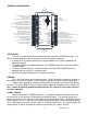
TERMINAL DESCRIPTIONS
CHECK ENGINE INDICATOR INPUT
BRAKE SYSTEM/PARKING BRAKE WARNING INPUT
HIGH BEAM INDICATOR INPUT
LEFT TURN SIGNAL INDICATOR INPUT
RIGHT TURN SIGNAL INDICATOR INPUT
4 WHEEL DRIVE INDICATOR INPUT
1-WIRE GEAR INDICATOR INPUT (FROM GSS UNIT)
WAIT TO START INDICATOR INPUT
CRUISE ENGAGED INDICATOR INPUT
FUEL LEVEL SENSOR GROUND OUTPUT
FUEL LEVEL SENSOR INPUT
NOT TYPICALLY USED
OIL PRESSURE SENSORGROUND OUTPUT
OIL PRESSURE SENSOR INPUT
OIL PRESSURE SENSORPOWER OUTPUT
WATER TEMPERATURE SENSOR GROUND OUTPUT
WATER TEMPERATURE SENSOR INPUT
NIGHT DIMMING ADJUSTMENT GROUND OUTPUT
NIGHT DIMMING ADJUSTMENT INPUT
SPEED SELECT SWITCH INPUT SW1
TACH SELECT SWITCH INPUT SW2
2000 PPM SPEED SIGNAL OUTPUT
VEHICLE SPEED SENSOR GROUND OUTPUT
VEHICLE SPEED SENSOR SIGNAL INPUT
VEHICLE SPEED SENSOR POWER OUTPUT
RPM WARNING/SHIFT OUTPUT
TACHOMETER INPUT
+12 VOLT ACCESSORY POWER INPUT
MAIN CHASSIS GROUND INPUT
STATUS LED
TO DISPLAY
CONNECTOR
(Doesn't matter which one)
ACC. POWER
CONST. POWER
GROUND
TACH
WARN
SPD +
SPD SND
SPD -
SPD OUT
SW2 (-)
SW1 (-)
ADJ SND
ADJ -
WTR SND
WTR -
OIL +
OIL SND
OIL -
RESERVED
(SEE MANUAL)
FUEL SND
FUEL -
WAIT (+)
CRUISE (-)
GEAR (1 WIRE)
4x4 (-)
RIGHT (+)
LEFT (+)
HIGH (+)
BRAKE (-)
CHECK ENG (-)
VHX
CONTROL BOX
CABLE
AUX.
I/O
DISPLAY
www.dakotadigital.com
techsupport@dakotadigital.com
605-332-6513
DIM (+)
NIGHT DIMMING INPUT
+12 VOLT CONSTANT POWER INPUT
STATUS LED
This LED is located at the corner of the control box, next to the GROUND terminal. The
LED is used for diagnostics and for a quick visual check if power is present.
A steady flash, on and off, about twice a second indicates the system is powered and
operating normally.
On steady indicates low power, below 9V, at the POWER terminals, or that the system is
in DEMO mode.
A short flash once every four seconds indicates the CONSTANT POWER terminal is
powered and the system is in stand-by mode.
Not flashing or lighting indicates loss of power or ground.
GROUND
This is the main ground for the display system. A wire should be run from this terminal to
the vehicle’s main chassis ground. Use 18 AWG or larger wire to ensure sufficient grounding.
Proper vehicle grounding is extremely important for any gauge (or electronics) to operate
correctly. The engine block should have heavy ground cables to the battery, frame, firewall, and
body. Failure to properly ground the engine block or the control box can cause incorrect
or erratic operation.
CONST. POWER
Connect the CONST. POWER terminal to a +12V power from the fuse panel that is “hot”
all of the time, or a fussed wire (5-20 amp) direct to battery power. This terminal should have
power all of the time. The constant +12V supply source should be a fused 5 - 20 amp circuit, the
system draws less than 1 amp, so sharing an existing constant power circuit will generally be fine.
Use 18 AWG wire to ensure the system receives a sufficient power feed. This terminal keeps the
clock memory as well as returning the needles to zero when the system is shut off.