
Installation Manual


MAN 650314:J
23
Custom fuel sender curve setup (custom)
You will need to have the sender out of the tank, or begin with the tank empty and
add fuel during the custom fuel sender setup.
*** The factory default custom curve is 110 empty and 5 ohms full
***You must select “
custom
” in the Fuel Sender menu after you have calibrated the custom
curve so the system knows that you want to use it.
When “CUSTOM” is displayed press and hold SW1 until the message screen changes.
The message display will show “custom --%” and “xxx OHMS”, release SW1.
The message display will show “custom 00%” and “xxx OHMS”, where xxx is the current
resistance the control box is seeing from the fuel sensor. You should be able to move
the float up and down at this point and see the resistance values follow the curve of
your sensor.
Now, with the float in the empty position, press and release SW1.
The message display will show “custom 33%” and “xxx OHMS”. Move the float to 1/3 full
and then press and release SW1.
The message display will show “custom 66%” and “xxx OHMS”. Move the float to 2/3 full
and then press and release SW1.
The message display will show “custom 99%” and “xxx OHMS”. Move the float to the full
position and then press and release SW1. The new sender is now stored under the
“CUSTOM” sender selection.
The message display will be back in the fuel sub-menu showing “FUEL test”.
***If the resistances recorded during custom calibration are not in sequence you will get a
“
FAIL
” message at the end of calibration. No values will be saved and calibration must be
started again. Make sure the resistance of the sensor is linear from empty to full.
Note: Once the custom sender is programmed, go back and ensure that “
custom
” is
selected in the “
FUEL SENDER”
menu. Programming the custom sender curve does not
automatically make it the ‘active’ sender.
Fuel sensor test (TEST)
This menu will allow you to check the resistance the control box is reading from the fuel
level sensor. This can be used as a diagnostic tool if you are having troubles or feel that the
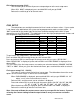
reading is incorrect. You can use the table of fuel sensors above to get an idea on the resistance
you should be seeing.
When “FUEL test” is displayed press and hold SW1 until the message screen changes.
Release SW1 and the current resistance from the fuel level sensor will be displayed as
“test fuel” “xxx ohms” where xxx is the resistance seen at the control box.
Press and release SW1 to scroll to other sensor inputs if you wish “temp” “oil” “Fuel”
Once complete, hold SW1 until “DONE” is displayed.
Release the switch to go onto the next sub-menu item.
Note: Fuel level sensors are generally not precise; in the test function you should expect to see
some error. For instance a GM 0-90 sensor may display 5 ohms empty and 97 ohms full. If you are
within 10% of the values in the table, this is considered within specification.
Exit fuel setup (done)
This will allow you to exit the fuel setup and go on to the next setup menu.
When “fuel done” is displayed, press and hold SW1 until “DONE” is displayed
Release the switch to go on to the next menu.