
Installation Manual


MAN 650314:J
5
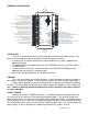
WIRING
While the control box contains several connections, the wiring is straightforward.
Depending on how many auxiliary functions you want displayed, not every terminal will be used in
most applications. On the pages that follow, we describe the function of each terminal, what they
do, and how to wire them.
MOMENTARY SW2
MOMENTARY SW1
CAT 5
CABLE
(TO DISPLAY)
DISPLAY PANEL
STATUS LED
DIM-1
Optional
Cruise Control
Engage Output
Glow Plug Relay
or
Wait to start output
ECU/ECM
check engine
output
BIM
CONNECTION
ONLY!
4x4
transfer case
switch
DAKOTA DIGITAL
GSS UNIT
1-Wire output
RIGHT TURN
SIGNAL WIRE
Optional
LEFT TURN
SIGNAL WIRE
HIGH BEAM
WIRE
PARKING BRAKE
SWITCH
SPEED OUT
(2k or 4k PPM)
Connect to tail light circuit,
LED backlights will turn on
when termianl has +12V
Light or Buzzer
(4 Watts or more)
Tail Light
Light or Buzzer
(4 Watts or less)
Relay
EXSISTING
FUEL LEVEL
SENSOR
RED
WHITE
BLACK
BLUE
BROWN
Additional ground wire to fuel
sensor body or mounting screw.
PRESSURE SENSOR
SEN-03-8
0-100 PSI
TEMP SENSOR
SEN-04-5
100-300 F
PULSE
GENERATOR
ECU/ECM
Speed Output
RED
WHITE
BLACK
+12V KEY ON POWER
(fused 5 - 20 AMP max)
Connect to main
chassis ground
Ignition Coil
(negative side)
- +
ECU/ECM
or Ignition Box
(tach output)
SPEED SENSOR
SEN-01-5
16k PPM
ACC. POWER
CONST. POWER
GROUND
TACH
WARN
SPD +
SPD SND
SPD -
SPD OUT
SW2 (-)
SW1 (-)
ADJ SND
ADJ -
WTR SND
WTR -
OIL +
OIL SND
OIL -
RESERVED
(SEE MANUAL)
FUEL SND
FUEL -
WAIT (+)
CRUISE (-)
GEAR (1 WIRE)
4x4 (-)
RIGHT (+)
LEFT (+)
HIGH (+)
BRAKE (-)
CHECK ENG (-)
VHX
CONTROL BOX
CABLE
AUX.
I/O
DISPLAY
www.dakotadigital.com
techsupport@dakotadigital.com
605-332-6513
DIM (+)
+12V CONSTANT POWER
(fused 5 - 20 AMP max)
BARE