SERIES II VACUUM FLUORESCENT DIGITAL DASHBOARD The latest in digital dashboard technology for the street rodder, car, and truck enthusiast. INSTALLATION AND OPERATION MANUAL Please read this before beginning installation or wiring. MODEL STR6D-GM 92-94 Chevrolet Full Size Pickup kit 3421 W. Hovland Ave.
Thank you for purchasing the Vacuum Fluorescent Digital Dashboard from DAKOTA DIGITAL, the leader in custom automotive electronics. Representing the latest electronics dashboard technology for the street rodder, car, and truck enthusiast alike, the digital instrumentation uses state of the art vacuum fluorescent display technology to give the driver up to date and accurate information on the operation of his or her vehicle.
INSTALLING THE DISPLAY SYSTEM The first step in installing your new digital gauge kit will be to remove the instrumentation cluster from your vehicle. The front plastic bezel must be removed first. Once this has been taken off, you can begin removing the instrument cluster. There are four screws which hold the instrument cluster in, two on each side. It may be necessary to move the heater vent duct or radio to get to the screws.
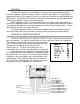
CONTROL BOX Once the display panel is in place, mount the control box within the connecting cable's distance (approximately 3 feet) and secure to the underside of the dashboard. This case does not have to be mounted to metal, but by doing so you will provide a better ground to the control box. When connecting the display cable to the unit, be very sure to pay attention to the "up" side of the connector. Align the connector in the socket and press firmly into the control box.
SPEED The BROWN wire from the display panel connects to the SPEED terminal. This system can accept 4000 ppm – 128000 ppm speed signals. The control box has been pre-calibrated to the 4000ppm signal from the display panel. The speedometer is fully adjustable and calibration is discussed in a later section. TACH Connect the tach terminal to the YELLOW wire coming from the display panel. DO NOT USE SOLID CORE SPARK PLUG WIRES WITH THIS DASHBOARD SYSTEM.
TRIP The TRIP terminal is used for the trip odometer function, for setting the oil warning set point (see WRN), and for speedometer calibration (see SPEEDOMETER CALIBRATION). The TRIP input is activated by a ground connection. The push button switch supplied (or any normally open switch) is wired by connecting one terminal to TRIP and the other terminal to a ground.
BRAKE The BRAKE terminal can be used as a brake system warning indicator. The BRAKE input is activated by a ground signal from the brake pressure switch on the master cylinder or from the parking brake set switch. Connect a wire from this terminal to the pressure switch on the master cylinder or consult a vehicle service manual to determine color and location of an existing wire. Whenever the BRAKE input is grounded the system will display a “b” to the left of the speedometer.
MPH/KPH The MPH/KPH terminal is activated by a 12 volt signal from a push button or toggle switch(not supplied). When the display system is in English mode (MPH & °F) by placing DIP programming switch #7 off, applying 12 volts to this terminal will convert the speed reading from MPH to KPH. The odometer will continue to accumulate miles correctly, but will display dashes. The bar speed display, if present, will not be affected.
Insert cable with red stripe to right side. Optional display power connector used only on STR4D/5D systems.
Setting up the control box SPEEDOMETER CALIBRATION The speedometer calibration is done using the TRIP and RESET switches. There are two different ways to calibrate the speedometer. The first method control box uses an auto-cal mode where you drive one mile (1 km for metric) and the system automatically adjusts the speedometer calibration. The second method allows you to adjust the speedometer up or down as you drive. To enter the auto-calibration mode, begin with the key off.
TACHOMETER DIP SWITCH SETTINGS The control box will work with 4, 6, 8, and 10 cylinder ignition systems. The DIP programming switches are located inside the control box, so the cover must be carefully removed to get access to the switches. Make sure the key is turned off before opening up the control box so that there is no power to the system. The switches numbers 5 and 6 select the number of engine cylinders.
GAUGE WARNING FEATURE The gauges have the built in feature to alert you when they are outside their normal operation range. The fuel display will flash whenever the fuel level is below 10% to indicate low fuel. The voltage gauge will flash whenever the system voltage is below 11.0 volts and the engine is running. The water gauge will flash whenever the temperature is higher than the water warning set point.
TROUBLESHOOTING GUIDE This is a list of some problems and their solutions which may be encountered when installing your instrumentation system. If you cannot determine what the problem is or how to solve it, please call our technical assistance line (605) 332-6513. * A note on vehicle grounding. * The most common cause of problems with electric gauges is poor ground connections. The engine block has the highest ground currents of any point in the vehicle.
Symptom Possible Problem Solution ----------------------------------------------------------------------------------------------------------------------------------The tachometer reading The tachometer signal wire is Check the connections at both is incorrect. loose or broken. ends of the wire. The control box is not set up for Refer to the Internal Adjustments the proper number of cylinders section of the installation manual or the proper tach range. to set the control box properly.
Symptom Possible Problem Solution ----------------------------------------------------------------------------------------------------------------------------------The gear shift indicator The optional gear shift sending Connect the sending unit to the does not light up. unit is not connected to the control box using the control box. instructions supplied with the sending unit. The gear shift indicator does not operate properly. The gear shift sending unit is not connected properly.