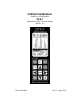
OPERATION MANUAL DAKOTA ULTRASONICS DFX-7 Material & Coating Thickness Gauge (Manual 1 of 2) P/N P-220-0004 Rev 1.
CHAPTER ONE INTRODUCTION ...................................................................... 1 CHAPTER TWO QUICK STARTUP GUIDE ....................................................... 2 CHAPTER THREE KEYBOARD, MENU, & CONNECTOR REFERENCE ....... 24 CHAPTER FOUR PRINCIPALS OF ULTRASONIC MEASUREMENT ............ 36 CHAPTER FIVE SELECTING THE MEASUREMENT MODE .......................... 41 CHAPTER SIX MAKING MEASUREMENTS ....................................................
CHAPTER ONE INTRODUCTION The Dakota Ultrasonics model DFX-7 is both, an ultrasonic thickness gauge, as well as a flaw detector. Since the DFX-7 is basically two gauges in a single package, we split the manual into two manuals, one for each gauge type. This manual will focus only on the thickness gauge portion of the gauge. The DFX-7 has the ability to simultaneously measure coatings and material thicknesses while maintaining the ability to locate pits, flaws and defects in the material.
CHAPTER TWO QUICK STARTUP GUIDE Turn the DFX-7 on and off using the switch located on the bottom right corner of the keypad. When DFX-7 is initially turned on, a flash logo and blinking lights will be displayed, followed by attempting to identify the transducer (probe) currently plugged into the gauge. The DFX-7 is equipped with an “Auto Probe Recognition” feature that attempts to identify special transducers with this built in feature.
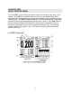
DFX-7 Ultrasonic Flaw Detector In order to understand how to operate the DFX-7, it’s best to start off with an understanding of what it is we’re looking at exactly. The DFX-7 has a lot of great features and tools that will prove to be a huge benefit for the variety of applications you’re constantly facing on a continual basis. Let’s have a brief look at the screens you’ll be looking at most often: A.
Dakota Ultrasonics F. Scan Bar – Another view of material thickness in a deflection style horizontal bar. This is a visual tool that would enable the user the ability to see thickness changes during high speed scans from flaws and pits. G. Units – The current measurement units being used (English, Metric). H. Digital Material Thickness Value – Smaller font size when the B-Scan display view is enabled. I.
DFX-7 Ultrasonic Flaw Detector 2.2 Auto Probe Recognition When the DFX-7 is initially powered up, the gauge will automatically check to see if the transducer plugged into the gauge can be recognized. The steps that follow assume the DFX-7 recognized the probe type: Probe Automatically Recognized 1) Press the OK key once to use the identified probe, or ESC to display a list of optional transducers.
Dakota Ultrasonics 3) Press the UP and DOWN arrow keys to toggle the coating option on/off. 4) Wipe all couplant from the transducer face and advance to the Probe Zero & Calibration section outlined below. 2.3 Selecting the Transducer Type If the DFX-7 does not identify a specific transducer type on initial power up, the user will be required to select a type from a predefined list of types by diameter and frequency.
DFX-7 Ultrasonic Flaw Detector Selecting the Transducer Type 1) Press the OK or ESC keys to display the factory list of transducer types (by diameter and frequency). 2) Press the UP and DOWN arrow keys to scroll through the transducer list until the appropriate type is highlighted.
Dakota Ultrasonics 3) Press the ENTER key to select the transducer type and display overwrite existing probe screen. 4) Press the OK key to overwrite the existing probe type with the newly selected probe type. The zero probe screen will be displayed. Proceed to the zero probe section that follows. 2.4 Probe Zero & Calibration The next steps are to perform a probe zero and calibrate the DFX-7 to the material and transducer being used.
DFX-7 Ultrasonic Flaw Detector Performing an Auto Probe Zero (Off Block) Coating Probe Identified Coating Probe Not Identified 1) Be sure all couplant has been removed from the face of the transducer. 2) Press the OK key to perform the automatic probe zero, or ESC key to cancel the zero operation. Coating Probe Identified Coating Probe Not Identified 3) The screens illustrated above will be briefly displayed followed by the main measurement screen. The DFX-7 is ready to be calibrated.
Dakota Ultrasonics Performing a Manual Probe Zero (On Block) Note: When the zero probe option is set to manual, the probe zero disk (battery cap) located on the top of the gauge, will be used as a zero standard and the warning screen illustrated above will be displayed. 1) Press the OK or ESC keys to enter the main measurement screen and begin the manual zero process.
DFX-7 Ultrasonic Flaw Detector Coating Probe Identified Coating Probe Not Identified 5) Press the ENTER key to display the confirmation screen. 6) If a coating transducer was identified use the UP and DOWN arrow keys to toggle coating on/off. 7) Press the OK key to complete the probe zero function, or ESC key to cancel the probe zero function. 8) Remove the transducer from the probe zero disk, and proceed to the calibration section.
Dakota Ultrasonics Using a Known Thickness Note: Be sure that the probe zero procedure has been performed prior to performing this calibration procedure. 1) Physically measure an exact sample of the material or a location directly on the material to be measured using a set of calipers or a digital micrometer. 2) Apply a drop of couplant on the transducer and place the transducer in steady contact with the sample or actual test material.
DFX-7 Ultrasonic Flaw Detector 4) Press the ENTER key to display the Digits Edit Box. 5) Press the UP and DOWN arrow keys to scroll the highlighted value. 6) Press the LEFT and RIGHT arrow keys to scroll the digit locations. 7) Repeat steps 5 & 6 until the known thickness value is correctly displayed. 8) Press the OK key to calculate the velocity and return to the menu screen, or ESC to cancel the one point calibration.
Dakota Ultrasonics Performing a Coating Zero 1) Press the MULTI MODE key once to activate the measurement mode options. 2) Use the UP and DOWN arrow keys to scroll through the sub menu items until Coating Only (CT) mode is highlighted. 3) Press the ENTER key to select the measurement mode and return to the measurement screen. 4) Apply a drop of couplant on the transducer and place the transducer in steady contact with the probe zero disk (battery cover) and obtain a steady reading.
DFX-7 Ultrasonic Flaw Detector 6) Use the UP and DOWN arrow keys to scroll through the sub menu items until ZERO COATING is highlighted. 7) Press the ENTER key to display the confirmation screen. 8) Press the OK key to zero the coating and return to the PRB menu, or ESC to cancel the coating zero process. 9) Press the MULTI MODE key once to activate the measurement mode options. 10) Use the UP and DOWN arrow keys to scroll through the sub menu items until Coating On (PECT) is highlighted.
Dakota Ultrasonics quick start section only the 1pt option PECT (pulse-echo coating) mode will be covered. Refer to the calibration section of the manual for a complete explanation on the coating calibration options.
DFX-7 Ultrasonic Flaw Detector 6) Repeat steps 4 & 5 until the velocity number is correctly displayed. 7) Press the OK key to set the coating velocity and return to the menu screen, or ESC to cancel entering the coating velocity. 8) Finally, press the MEAS key to return to the measurement screen and begin taking readings.
Dakota Ultrasonics Important Note: In PECT (pulse-echo coating) mode, the coating sample must be coupled to metal in order to calibrate successfully. Simply place a drop of couplant on a piece of metal, lay the coating sample over the couplant on the metal and proceed to step 2. 2) Apply a drop of couplant on the transducer and place the transducer in steady contact with the coating (on metal) sample or actual test material.
DFX-7 Ultrasonic Flaw Detector 8) Press the OK key to calculate the coating velocity and return to the menu screen, or ESC to cancel the one point calibration. 9) Finally, press the MEAS key to return to the measurement screen and begin taking readings. Note: CHECK YOUR CALIBRATION! Place the transducer back on the calibration point. The coating thickness reading should now match the known coating thickness sample. If the thickness is not correct, repeat the steps above. 2.
Dakota Ultrasonics 2) Use the UP and DOWN arrow keys to scroll through the sub menu items until VIEW is highlighted. 3) Use the LEFT and RIGHT arrow keys to scroll the view options. 4) Once the view is displayed, press the MEAS key to return to measurement mode. DIGITS: Displays the digital thickness value using a large font size. This view is useful when the DFX-7 is being used as a basic thickness gauge.
DFX-7 Ultrasonic Flaw Detector Adjusting Delay (B-Start) & Range (B-DEPTH) 1) Press the MEAS key once to activate the measure menu items. Press the MEAS key multiple times to move right and the ESC key multiple times to move left, until the either the DELAY (START) or RANGE (DEPTH) cell is highlighted. 2) Use the UP, DOWN, LEFT, or RIGHT arrow keys to scroll the DELAY (START) and RANGE (DEPTH) values. 3) Repeat steps 1 & 2 until the range is correctly being displayed.
Dakota Ultrasonics 1) Press the ENTER key to display the digits edit box. 2) Press the UP and DOWN arrow keys to scroll the highlighted value. 3) Press the LEFT and RIGHT arrow keys to scroll the digit locations. 4) Repeat steps 3 & 4 until the DELAY (START) or RANGE (DEPTH) value is correctly displayed. 5) Press the OK key to set the DELAY (START) and WIDTH (DEPTH) value and return to the measure screen, or ESC to cancel entering the DELAY (START) or WIDTH (DEPTH) value.
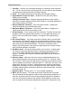
DFX-7 Ultrasonic Flaw Detector RF View Rectified (RECT) View BSCAN View DIGITS View In the upper left corner of each of the display photos above, is the repeatability indicator. The repeatability indicator is represented by six vertical bars and represents how repeatable the measurements are. In regular measurement mode, the DFX-7 makes 8 measurements a second. In scan mode, the DFX-7 makes 200 measurements a second.
CHAPTER THREE KEYBOARD, MENU, & CONNECTOR REFERENCE 3.1 Menu Key (Operation & Sub Menus) The Menu key activates the primary menu structure containing 8 menu tab groups. These tab groups then contain sub menu items, or functions. The sub menu items have been organized in tab groups according to how closely they are related to the individual tab group names. Let’s first get familiar with how to move around in these tabs before continuing on to the sub menu functions.
DFX-7 Ultrasonic Thickness Gauge Activating and Getting Around in the Menu Items 1) Press the MENU key once to activate the menu items tab. Press the MENU key multiple times to tab right, and the ESC key multiple times to tab left until the desired tab group is highlighted and displaying the submenu items (B). The tab groups are illustrated above (A).
Dakota Ultrasonics 3.2 Probe – Menu ZERO PROBE: The DFX-7 is zeroed in much the same way that a mechanical micrometer is zeroed. If the DFX-7 is not zeroed correctly, all of the measurements made using the DFX-7 may be in error by some fixed value. The DFX-7 is equipped with an optional automatic or manual zero feature. Refer to the section on page 48, for an explanation of this important procedure.
DFX-7 Ultrasonic Thickness Gauge COATING 2PT: Performs a two-point coating calibration. This option allows the user to automatically calculate the velocity by entering a second known coating sample thickness. Refer to page 104 for further info. COATING VEL: Function to calibrate the DFX-7 to a specific coating material type by entering a coating velocity. Refer to page 16 or page 98 for further info. 3.
Dakota Ultrasonics 3.5 TUNE – Menu MEASURE MODE: Toggles a variety of unique measurement modes for different application requirements: Coating Off (P-E), Coating On (PECT), Temp Comp (PETP), Thru Coat (E-E), Thru Verify (E-EV), Coating Only (CT). Refer to page 37 for further info. POLARITY: The DFX-7 operates on a zero crossing detection principle. This feature toggles which stroke of the cycle the crossing detection uses, either positive or negative. Refer to page 115 for further info.
DFX-7 Ultrasonic Thickness Gauge 3.6 GT1 – Menu GATE1: Gates allow the user to view a specific measurement range, or sections of the waveform, and ignore others. The Gate1 feature adjusts the start of the gate, according to time/distance. Gate 1 can be used in all pulse-echo and echo-echo measurement modes. Refer to page 83 for further info. GATE1 WIDTH: This feature allows the user to set the overall width of the gate, in terms of distance, from the starting value of Gate1.
Dakota Ultrasonics HOLDOFF 3: Provides the user with the ability to delay the starting point of Gate3, a specific distance from the first detection point found inside of the boundaries of the Gate 2 settings. If no detection is found, the Gate2 width value is used as a starting value for Gate3. Refer to page 83 for further info. THRESHOLD3: Enables the user to set the sensitivity level of Gate3. The amplitude of the signal must reach or exceed the threshold level before a measurement is detected.
DFX-7 Ultrasonic Thickness Gauge EDIT: Gives the user the ability to change parameters of grid or sequential file previously saved. Note: Pre-defined coordinates cannot be changed once they have been created. Refer to page 147 for further info. OPEN: This function provides the user with the ability to recall grids or sequential log files that currently exist in memory, from a list of grids. Refer to page 149 for further info.
Dakota Ultrasonics 3.12 XFER (transfer) – Menu BACKUP SETUPS: Enables the user the ability to backup the setups currently stored in the DFX-7 to a PC via RS232 port. Refer the help section of the DFX-7 DakView software for a complete electronic manual. RESTORE SETUPS: Enables the user the ability to restore the setups currently saved on a PC to an DFX-7 via RS232 port. Refer the help section of the DFX-7 DakView software for a complete electronic manual.
DFX-7 Ultrasonic Thickness Gauge 3.15 OK Key The primary function of the OK key is confirmation of a change or selection. The OK key also toggles the Hot Menu area, while in measurement mode, to a large digits display area. If the DFX-7 is displaying a grid log, the OK key toggles an advance to row number option. 3.16 ESC Key The ESC key is used in the MENU, MEAS, and EDIT functions as a back or escape function.
Dakota Ultrasonics 3.20 ON/OFF Key The ON/OFF key simply powers the unit either ON or OFF. Note: Unit will automatically power off when idle for 5 minutes. All current settings are automatically saved, prior to powering off.
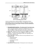
3.21 Top & Bottom End Caps The top & bottom end panels are where all connections are made to the DFX-7. The diagram above shows the layout and description of the connectors: Transducer Connectors Refer to Diagram: The transducer connectors and battery cover/probe zero disk are located on the DFX-7’s top end cap. The transducer connectors are of type Lemo “00”. Note: There is no polarity associated with connecting the transducer to the DFX-7.
CHAPTER FOUR PRINCIPALS OF ULTRASONIC MEASUREMENT 4.1 Time versus thickness relationship Ultrasonic thickness measurements depend on measuring the length of time it takes for sound to travel through the material being tested. The ratio of the thickness versus the time is known as the sound velocity. In order to make accurate measurements, a sound velocity must be determined and entered into the instrument. The accuracy of a thickness measurement therefore depends on having a consistent sound velocity.
DFX-7 Ultrasonic Thickness Gauge through air efficiently. By using a liquid couplant between the transducer and test piece the amount of ultrasound entering the test piece is much greater. 4.5 Temperature Temperature has an effect on sound velocity. The higher the temperature, the slower sound travels in a material. High temperatures can also damage transducers and present a problem for various liquid couplants.
Dakota Ultrasonics V-Path Correction Dual element delay line transducers have two piezoelectric elements mounted at an angle on one end of the delay line. One element is used for transmitting sound, while the other element only receives sound. The two elements and their delay lines are packaged in a single housing but acoustically isolated from each other with a sound barrier. This allows the transducer the ability to achieve very high sensitivity for detecting small defects.
DFX-7 Ultrasonic Thickness Gauge Dual Element Transducer in Echo to Echo mode Echo-Echo Verify Mode – Thru-Verify (E-EV) The echo-echo verify mode measures between 3 reflections. Similar to E-E mode, this technique is commonly used to eliminate errors from surface coatings and also to make measurements in multiple layered materials.
Dakota Ultrasonics Pulse-Echo Temperature Compensated Mode – Temp Comp (PETP) This is a custom mode that combines pulse-echo and electronic zero techniques to automatically adjust for temperature changes in the transducer as a result of an increasing/decreasing temperature gradient in the test material. Note: rough surface conditions can have an effect on the overall accuracy in this mode.
CHAPTER FIVE SELECTING THE MEASUREMENT MODE 5.1 The setup library The DFX-7 contains 64 user configurable preset locations to store custom setups for easy recall. These setups can be optimized for the user’s specific application needs and can also be stored on a PC and transferred bi-directionally using Dakota’s PC interface software included with the instrument. The setups supplied with the instrument cover some of the more typical applications commonly used with this type of instrument.
Dakota Ultrasonics Thru Paint & Coatings Often times, users will be faced with applications where the material will be coated with paint or some other type of epoxy material. Since the velocity of the coating is approximately 2.5 times slower than that of steel, pulse-echo mode will induce error if the coating or paint is not completely removed.
DFX-7 Ultrasonic Thickness Gauge Restricted access Measuring materials with extreme curvatures or restricted access, higher frequencies with smaller diameters should be considered. The smallest diameter uses 3/16” crystals with a contact area of .250”. Custom transducers are available on request. 5.
CHAPTER SIX MAKING MEASUREMENTS The steps involved in making measurements are detailed in this section. The following sections outline how to setup and prepare your DFX-7 for field use. An automatic or manual zero must always be performed. The auto zero is an off block electronic zero that does not require a zero reference block. This will most always be the zero option of choice, as it makes the zeroing process very easy and convenient to perform.
DFX-7 Ultrasonic Thickness Gauge In this first example the transducer was automatically identified: Probe Automatically Recognized 1) Press the OK key once to use the identified probe, or ESC to display a list of optional transducers. Note: if the DFX-7 recognizes a specific transducer, the user should always select OK to use the identified probe.
Dakota Ultrasonics 3) Press the UP and DOWN arrow keys to toggle the coating option on/off. 4) Wipe all couplant from the transducer face and proceed to the Probe Zero section that follows. In this second example the transducer was not identified and will force the user to select the transducer type from a predefined list of transducers: Selecting the Transducer Type 5) Press the OK or ESC keys to display the factory list of transducer types (by diameter and frequency).
DFX-7 Ultrasonic Thickness Gauge 6) Press the UP and DOWN arrow keys to scroll through the transducer list until the appropriate type is highlighted. 7) Press the ENTER key to select the transducer type and display overwrite existing probe screen. 8) Press the OK key to overwrite the existing probe type with the newly selected probe type. The zero probe screen will be displayed. Proceed to the zero probe section that follows.
Dakota Ultrasonics 6.2 Probe zero The next step is to perform a probe zero. The zero function is a very important and necessary function that must be done prior to calibration. It should be done on a regular basis. In fact, the DFX-7 has been programmed to force this issue at regular intervals during operation if it hasn’t been done. If the DFX-7 is not zeroed correctly, all the measurements taken may be in error by some fixed value.
DFX-7 Ultrasonic Thickness Gauge 2) Press the OK key to perform the automatic probe zero, or ESC key to cancel the zero operation. Coating Probe Identified Coating Probe Not Identified 3) The screens illustrated above will be briefly displayed followed by the main measurement screen. The DFX-7 is ready to be calibrated.
Dakota Ultrasonics Performing a Manual Probe Zero (On Block) Note: When the zero probe option is set to manual, the probe zero disk (battery cap) located on the top of the gauge will be used as a zero standard and the warning screen illustrated above will be displayed. 1) Press the OK or ESC keys to enter the main measurement screen and begin the manual zero process.
DFX-7 Ultrasonic Thickness Gauge Coating Probe Identified Coating Probe Not Identified 5) Press the ENTER key to display the confirmation screen. 6) If a coating transducer was identified use the UP and DOWN arrow keys to toggle coating on/off. 7) Press the OK key to complete the probe zero function, or ESC key to cancel the probe zero function. 8) Remove the transducer from the probe zero disk, and proceed to the calibration section.
Dakota Ultrasonics all of the measurements the gauge makes will be erroneous by some fixed percentage. The One Point calibration is the simplest and most commonly used calibration method - optimizing linearity over large ranges. The Two Point calibration allows for greater accuracy over small ranges by calculating the probe zero and velocity.
DFX-7 Ultrasonic Thickness Gauge 3) Press the ENTER key to display the Digits Edit Box. 4) Press the UP and DOWN arrow keys to scroll the highlighted value. 5) Press the LEFT and RIGHT arrow keys to scroll the digit locations. 6) Repeat steps 4 & 5 until the velocity number is correctly displayed. 7) Press the OK key to set the velocity and return to the menu screen, or ESC to cancel entering the velocity. 8) Finally, press the MEAS key to return to the measurement screen and begin taking readings.
Dakota Ultrasonics Known Thickness Sometimes the sound velocity of a material is unknown. In this case a sample with one or two known thicknesses can be used to determine the sound velocity. As previously discussed, the DFX-7 has a one or two point calibration option. The one point calibration option is most suited for linearity over large ranges, as noted above.
DFX-7 Ultrasonic Thickness Gauge ESC key multiple times to tab left until the CAL menu is highlighted and displaying the submenu items. 3) Use the UP and DOWN arrow keys to scroll through the sub menu items until MATL 1PT is highlighted. 4) Press the ENTER key to display the Digits Edit Box. 5) Press the UP and DOWN arrow keys to scroll the highlighted value. 6) Press the LEFT and RIGHT arrow keys to scroll the digit locations. 7) Repeat steps 5 & 6 until the known thickness value is correctly displayed.
Dakota Ultrasonics the job. For example, if the measurement range was .080” (2.03mm) to .250” (6.35mm), the user would perform a one point calibration on a known thickness sample close to .250” (6.35mm), followed by a two point calibration close to .080” (2.03mm). When a two point calibration is performed, the DFX-7 calculates the zero and the velocity.
DFX-7 Ultrasonic Thickness Gauge 4) Press the ENTER key to display the Digits Edit Box. 5) Press the UP and DOWN arrow keys to scroll the highlighted value. 6) Press the LEFT and RIGHT arrow keys to scroll the digit locations. 7) Repeat steps 5 & 6 until the known thickness value is correctly displayed. 8) Press the OK key to calculate the velocity and return to the menu screen, or ESC to cancel the one point calibration.
Dakota Ultrasonics being tested. Use these values only if a close approximation is acceptable. Follow the steps below to select a basic material type: Selecting a Basic Material Type 1) Press the MENU key once to activate the menu items tab. Press the MENU key multiple times to tab right and the ESC key multiple times to tab left until the CAL menu is highlighted and displaying the submenu items. 2) Use the UP and DOWN arrow keys to scroll through the sub menu items until MAT is highlighted.
DFX-7 Ultrasonic Thickness Gauge 4) Press the UP and DOWN arrow keys to scroll through the material list until the appropriate material is highlighted. 5) Press the ENTER key to overwrite the material type and display the menu items with the new material type selected. 6) Finally, press the MEAS key to return to the measurement screen and begin taking readings.
CHAPTER SEVEN USING THE DISPLAY OPTIONS A key feature of the DFX-7 is the ability to toggle between four different display options; Digits, RF, RECT and B-Scan. All views provide a digital readout of base material and coating thickness measurements, while also displaying the alarm tolerances, if active. A key feature of the DFX-7 is the waveform display. The waveform is a graphical representation of the sound reflections returning to the transducer.
DFX-7 Ultrasonic Thickness Gauge 7.1 Display Views DIGITS VIEW DIGITS The Digits view is a basic digital thickness gauge look and feel. The larger digits make it much easier for the operator to monitor the thickness readings. The Scan Bar has also been added to the Digits view to provide the user with yet another visual tool for easily monitoring changes in thickness readings due to internal flaws or defects. The following is a list of the viewable features on the display: A.
Dakota Ultrasonics E. F. G. H. I. J. Alarm Mode (ON/OFF/AUDIBLE) Gain Setting (VLOW, LOW, MED, HI, VHI) Digital Material Thickness Value – Extra large font size for viewing ease. Scan Bar – Another view of material thickness in a deflection style horizontal bar. This is another visual tool that would enable the user the ability to see thickness changes during high speed scans from flaws and pits. Units – The current measurement units being used (English, Metric).
DFX-7 Ultrasonic Thickness Gauge the user would see is a black screen from 0.00” – 1.00” with no view of the bottom contour at 1.75”. The following is a list of the viewable features on the display: A. Repeatability/Stability Indicator – This indicator should be commonly used in conjunction with the digital thickness values displayed.
Dakota Ultrasonics RF A-Scan View Radio Frequency (RF) A-Scan The RF mode shows the waveform in a similar fashion to an oscilloscope. It shows both the positive and the negative peaks. The peak (either positive or negative) selected for measurement is shown in upper portion of the display. It’s important to note that a measurement must fall inside the displays viewable range in order to see the waveform.
DFX-7 Ultrasonic Thickness Gauge E. Gate – An electronic feature that allows the user to monitor signals inside the boundaries of the gate settings. The height of the gate from the baseline is known as the threshold, and controls the sensitivity of the reflections that trigger a detection from the opposite surface of the material. F. Measurement Scale – Represents thickness values over a defined measurement range, and labeled at the calibrated hash marks on the display (X) axis. G.
Dakota Ultrasonics RECT A-Scan View Rectified (RECT) A-Scan The RF mode shows the waveform in a similar fashion to an oscilloscope. It shows both the positive and the negative peaks. The peak (either positive or negative) selected for measurement is shown in upper portion of the display. It’s important to note that a measurement must fall inside the displays viewable range in order to see the waveform.
DFX-7 Ultrasonic Thickness Gauge E. Gate – An electronic feature that allows the user to monitor signals inside the boundaries of the gate settings. The height of the gate from the baseline is known as the threshold, and controls the sensitivity of the reflections that trigger a detection from the opposite surface of the material. F. Measurement Scale – Represents thickness values over a defined measurement range, and labeled at the calibrated hash marks on the display (X) axis. G.
Dakota Ultrasonics 7.2 Changing Display Options The following procedure outlines how to select or toggle display options: Changing Display Options Color VGA 1) Press the MENU key once to activate the menu items tab. Press the MENU key multiple times to tab right, and the ESC key multiple times to tab left, until the DISP menu is highlighted and displaying the submenu items. 2) Use the UP and DOWN arrow keys to scroll through the sub menu items until VIEW is highlighted.
DFX-7 Ultrasonic Thickness Gauge 7.3 Adjusting the display This section will cover the procedures for adjusting the viewable range, or area, of the display, in terms of thickness. A basic overview of this section would be as follows: Suppose we had a 50” widescreen television set. Assume that you’re watching the television for rest of this explanation. The left side of the television screen is considered the Delay for all view options other than B-Scan. In B-Scan view, it’s called B-Start.
Dakota Ultrasonics Adjusting Delay (B-Start) using the Hot Menus 1) Press the MEAS key once to activate measure menu items. Press the MEAS key multiple times to move right and the ESC key multiple times to move left, until the DELAY cell is highlighted. 2) Press the UP, DOWN, LEFT, and RIGHT arrow keys to scroll the highlighted value. 3) Alternatively, press the ENTER key to display the Digits Edit Box. 4) Press the UP and DOWN arrow keys to scroll the highlighted value.
DFX-7 Ultrasonic Thickness Gauge 5) Press the LEFT and RIGHT arrow keys to scroll the digit locations. 6) Repeat steps 4 & 5 until the DELAY value is correctly displayed. 7) Press the OK key to return to the measurement screen, or ESC to cancel entering the DELAY. 8) Finally, press the MEAS key to return to the measurement screen and begin taking readings. Adjusting the Range (B-Depth) Once again, just to reiterate, the Range (B-Depth) + Delay (B-Start) equals the right side of the screen.
Dakota Ultrasonics 2) Press the UP, DOWN, LEFT, and RIGHT arrow keys to scroll the highlighted value. 3) Alternatively, press the ENTER key to display the Digits Edit Box. 4) Press the UP and DOWN arrow keys to scroll the highlighted value. 5) Press the LEFT and RIGHT arrow keys to scroll the digit locations. 6) Repeat steps 4 & 5 until the WIDTH value is correctly displayed. 7) Press the OK key to return to the measurement screen, or ESC to cancel entering the WIDTH.
Adjusting the B-Scan Speed The DFX-7 has the capability to adjust the the scrolling speed of the time based BScan displayed in the gauge. The procedures to adjust the speed are outlined below: Adjusting the B-Scan Speed 1) Press the MENU key once to activate the menu items tab. Press the MENU key multiple times to tab right, and the ESC key multiple times to tab left, until the DISP menu is highlighted and displaying the submenu items.
Dakota Ultrasonics 8) Press the OK key to set the speed and return to the DISP menu., followed by pressing the MEAS key to begin the B-Scan process. 9) Finally, press the MEAS key to return to the measurement screen and begin the scanning process. 7.4 Gain The gain, or amplification of the return echoes, can be adjusted in the DFX-7 to accommodate a variety of applications. The setting of the gain is crucial in order to obtain valid readings during the measurement process.
DFX-7 Ultrasonic Thickness Gauge Note: When the echo-echo thru-paint, or echo-echo-verify measurement modes are selected, the manual gain feature is disabled and grayed out in the menu items. In this mode, the DFX-7 switches to an automatic gain mode (AGC) that optimizes the gain setting automatically in the hardware of the DFX-7. The procedures to adjust the Gain are outlined below: Adjusting the Gain using the Hot Menus 1) Press the MEAS key once to activate measure menu items.
Dakota Ultrasonics 3) Alternatively, press the ENTER key to display the Digits Edit Box. 4) Press the UP and DOWN arrow keys to scroll the highlighted value. 5) Press the LEFT and RIGHT arrow keys to scroll the digit locations. 6) Repeat steps 4 & 5 until the GAIN value is correctly displayed. 7) Press the OK key to return to the measurement screen, or ESC to cancel entering the GAIN.
DFX-7 Ultrasonic Thickness Gauge The user can also access and adjust the gain from the tabbed menus. However, this method is more tedious than making the adjustments using the Hot Menus. The procedure using the tabbed menus is outlined below: Adjusting the Gain using the Tabbed Menus 1) Press the MENU key once to activate the menu items tab. Press the MENU key multiple times to tab right, and the ESC key multiple times to tab left, until the TUNE menu is highlighted and displaying the submenu items.
Dakota Ultrasonics 4) Alternatively, press the ENTER key to display the Digits Edit Box. 5) Press the UP and DOWN arrow keys to scroll the highlighted value. 6) Press the LEFT and RIGHT arrow keys to scroll the digit locations. 7) Repeat steps 5 & 6 until the Gain value is correctly displayed. 8) Press the OK key to set the Gain and return to the menu screen, or ESC to cancel entering the Gain. 9) Finally, press the MEAS key to return to the measurement screen and begin taking readings.
DFX-7 Ultrasonic Thickness Gauge 7.5 Threshold The Threshold is the level (sensitivity) of the signal amplitude required to trigger the thickness reading. This level can be used in conjunction with the gain. Example: suppose the user can visually see a potential flaw on the display, but the DFX-7 is not detecting on the flaw because the Gain is too low, or the Threshold to high. The Threshold level can be decreased (lower sensitivity) in order to detect signals with lower amplitudes.
Dakota Ultrasonics 2) If the correct THRESHOLD is displayed, press the UP, DOWN, LEFT, and RIGHT arrow keys to scroll the highlighted value. 3) Alternatively, if the correct Threshold is not being displayed, press the ENTER key to display the List Box. 4) Use the UP and DOWN arrow keys to scroll through the List Box items until the correct THRESHOLD is highlighted. 5) Press the MEAS key to return to the measure screen and Hot Menu items.
DFX-7 Ultrasonic Thickness Gauge 1) Press the MENU key once to activate the menu items tab. Press the MENU key multiple times to tab right, and the ESC key multiple times to tab left, until the GT1 menu is highlighted and displaying the submenu items. 2) Use the UP and DOWN arrow keys to scroll through the sub menu items until THRESHOLD1 is highlighted. 3) Press the LEFT and RIGHT arrow keys to scroll the value. When the correct threshold is being displayed, proceed to step 8.
Dakota Ultrasonics 10) Finally, press the MEAS key to return to the measurement screen and begin taking readings.
DFX-7 Ultrasonic Thickness Gauge 7.6 Understanding the features of the Gate Important: It is recommended to spend some time in this section. The sections that follow are procedures for using the features associated with the Gates, in some way. There are 3 gates in the DFX-7, and as a result, operating and setting them up can become somewhat convoluted, to say the least.
Dakota Ultrasonics pulse, or in the material, the gate can be moved to the right of the noise and block the unwanted noise. Gates 2 and 3 will automatically start from the end of gate 1, or from a detection found inside of the boundaries of gate 1. Therefore, we use a holdoff delay as a start feature for gates 2 and 3. See Diagram 2. Hold-Off: The hold-off is the starting point of the left side of gates 2 & 3, and is used only if a detection is found inside the previous gate.
DFX-7 Ultrasonic Thickness Gauge Activating the gates: Automatically: The gates are automatically activated, when a measurement mode is selected. Gate1 is active in all measurement modes. These modes have been internally setup at the Dakota factory. Therefore, if the user selects the Thru Coat (E-E) option, an internal setup will be loaded, and 2 gates will automatically be activated. This setup will work fine for the majority of all common applications.
Dakota Ultrasonics 7.7 Gates The DFX-7 is equipped with 3 gates, as explained in the previous section. One gate is active at all times in every measurement mode, with the exception of coating mode. These gates are full featured and completely adjustable. They can be fine tuned by the user to accommodate a variety of application scenarios. Diagram 1 in the previous section outlines the gates and features available for all measurement modes. Refer to the previous section for additional information.
DFX-7 Ultrasonic Thickness Gauge Example of Surface or Transducer Noise Noise Blocked The diagrams above illustrate a typical surface noise condition. Refer to the Noise diagram: (A) refers to the noise in front of the actual back wall signal (C). Notice the start position of the gate. As a result, the DFX-7 is detecting on the noise (A) as shown at point (B). However, the true measurement should be taken at point (C).
Dakota Ultrasonics Note: This is a combined procedure that works the same for any of the features associated with the gates, regardless of which feature and gate number that is being adjusted. Therefore (Ж) = Gate1, Hold-Off, and Width respectively. Finally, the illustrations may not be applicable to the exact feature being adjusted, but the concepts relevant. Adjusting the Features of the Gates Using the Hot Menus Gate Holdoff ‘s Width’s 1) Press the MEAS key once to activate measure menu items.
DFX-7 Ultrasonic Thickness Gauge 4) Use the UP and DOWN arrow keys to scroll through the List Box items until the correct (Ж) is highlighted. 5) Press the MEAS key to return to the measure screen and Hot Menu items. 6) Press the UP, DOWN, LEFT, and RIGHT arrow keys to scroll the highlighted value. 7) Repeat steps 3-6 until all the (Ж) values are correctly adjusted. The user can also access and adjust the (Ж) from the tabbed menus.
Dakota Ultrasonics 4) Alternatively, press the ENTER key to display the Digits Edit Box. 5) Press the UP and DOWN arrow keys to scroll the highlighted value. 6) Press the LEFT and RIGHT arrow keys to scroll the digit locations. 7) Repeat steps 5 & 6 until the (Ж) number is correctly displayed. 8) Press the OK key to set the (Ж) and return to the menu screen, or ESC to cancel entering the (Ж). 9) Repeat steps 1-8 to set any additional (Ж) level.
CHAPTER EIGHT THRU PAINT MEASUREMENT TECHNIQUE 8.1 Introduction to Thru Paint Measurement The principle behind thru paint measurement is by measuring the time between two backwall echoes returning from the test material. Since both of these backwall echoes travel the same path through the paint or coating, the thickness of the coating is subtracted out of the measurement so that only the actual material thickness can be measured.
Dakota Ultrasonics mode button on the keypad. The DFX-7 has been programmed to identify the modes available to a specific transducer. When configuring the DFX-7 for specific thru paint applications, all of the scope parameters will potentially be needed. The delay, range, gain (AGC), thresholds, gates, and hold-offs will be subject to change. For this reason, they have all been added to Hot Menu fields located directly beneath the A-Scan display for quick and easy access.
DFX-7 Ultrasonic Thickness Gauge at point (C) in the incorrect diagram, to point (B) in the correct diagram. If we adjust the GATE2 hold-off further to the right of the first reflection, the ring down noise from the first back wall echo no longer interferes with the true detection (D), shown in the correct diagram. The adjustment considerations in the example above will typically be used for all thru paint applications respectively.
CHAPTER NINE PULSE-ECHO COATING & COATING TECHNIQUES 9.1 Introduction to Pulse-Echo Coating Measurement (PECT) In the previous sections we’ve discussed the need for detecting pits and flaws (pulseecho) in materials, along with the requirement to measure through and eliminate errors caused by coated materials (echo-echo). Until now, both modes were needed in order accomplish both tasks.
DFX-7 Ultrasonic Thickness Gauge 3) From the tabbed menus under TUNE, MEASURE MODE. The steps that follow will demonstrate all three methods in the order listed above: Probe Automatically Recognized (PECT only) 1) Press the OK key once to use the identified probe, or ESC to display a list of optional transducers. Note: if the DFX-7 recognizes a specific transducer, the user should always select OK to use the identified probe.
Dakota Ultrasonics 3) Press the UP and DOWN arrow keys to toggle the coating option on/off. Multi Mode Key Pressed (PECT & CT) Applied to Metals Not Applied to Metals 1) Press the MULTI MODE key located on bottom left of the keypad to display the MEASURE MODE options menu. 2) Press the UP and DOWN arrow keys to highlight the COATING ON (PECT) or COATING ONLY (CT) menu option.
DFX-7 Ultrasonic Thickness Gauge 3) Press the ENTER key to enable the coating option, or ESC to cancel changing the measure mode, and return to the main measurement screen. Measure Mode (Tabbed Menus) – (PECT & CT) Applied to Metals Not Applied to Metals 1) Press the MENU key once to activate the menu items tab. Press the MENU key multiple times to tab right, and the ESC key multiple times to tab left, until the TUNE menu is highlighted and displaying the submenu items.
Dakota Ultrasonics 9.3 Zero Coating In order to account for very slight electronic differences in transducers of the same type, frequency, and diameter, the DFX-7 has been equipped with a “zero coating” feature. This enables the DFX-7 to obtain very accurate readings on coatings, eliminating potential errors incurred from slight differences in the manufacturing processes. The procedure is outlined below: Performing a Coating Zero 1) Press the MULTI MODE key once to activate the measurement mode options.
DFX-7 Ultrasonic Thickness Gauge 5) Press the MENU key once to activate the menu items tab. Press the MENU key multiple times to tab right and the ESC key multiple times to tab left until the PRB menu is highlighted and displaying the submenu items. 6) Use the UP and DOWN arrow keys to scroll through the sub menu items until ZERO COATING is highlighted. 7) Press the ENTER key to display the confirmation screen.
Dakota Ultrasonics 9.4 Coating Calibration (PECT) Known Velocity If the coating velocity is known, the user may wish to simply enter the velocity number into the DFX-7, rather than have the DFX-7 calculate the velocity value using a known thickness on a coating sample(s). The steps for entering the velocity are outlined below: Using a Known Material Velocity 1) Press the MENU key once to activate the menu items tab.
DFX-7 Ultrasonic Thickness Gauge 3) Press the ENTER key to display the Digits Edit Box. 4) Press the UP and DOWN arrow keys to scroll the highlighted value. 5) Press the LEFT and RIGHT arrow keys to scroll the digit locations. 6) Repeat steps 4 & 5 until the velocity number is correctly displayed. 7) Press the OK key to set the velocity and return to the menu screen, or ESC to cancel entering the velocity. 8) Finally, press the MEAS key to return to the measurement screen and begin taking readings.
Dakota Ultrasonics Known Thickness Sometimes the sound velocity of a coating material is unknown. In this case a sample with a known thickness can be used to determine the sound velocity of the coating. As previously discussed, the DFX-7 offers a one point calibration option for coating in PECT measurement mode. It is also import to reiterate that the coating sample must be coupled to a metallic material in order to perform the calibration.
DFX-7 Ultrasonic Thickness Gauge and place the transducer in steady contact with the coating and sample or actual test material. Be sure that the reading is stable and the repeatability indicator, in the top left corner of the display, is fully lit and stable. Press the MENU key once to activate the menu items tab. Press the MENU key multiple times to tab right and the ESC key multiple times to tab left until the CAL menu is highlighted and displaying the submenu items.
Dakota Ultrasonics Note: CHECK YOUR CALIBRATION! Place the transducer back on the calibration point. The coating thickness reading should now match the known thickness. If the thickness is not correct, repeat the steps above. 9.5 Introduction to Coating Measurement (CT) In the previous sections we’ve discussed how to setup and use the coating feature for use in conjunction with material thickness for flaw and pit detection. The DFX-7 also has the capability to be used for general coating measurements.
DFX-7 Ultrasonic Thickness Gauge One Point Calibration Note: Use the maximum coating sample for the one point calibration first. 1) Physically measure the thicker of the two samples of coating, as close as possible to the maximum expected coating measurement range, using a set of calipers or a digital micrometer. Very Important: If coating measurements will be made with the coating applied to a metal surface, the calibration must be done in the same manner, with the samples coupled to a metal surface.
Dakota Ultrasonics 3) Use the UP and DOWN arrow keys to scroll through the sub menu items until COATING 1PT is highlighted. 4) Press the ENTER key to display the Digits Edit Box. 5) Press the UP and DOWN arrow keys to scroll the highlighted value. 6) Press the LEFT and RIGHT arrow keys to scroll the digit locations. 7) Repeat steps 5 & 6 until the known thickness value is correctly displayed.
DFX-7 Ultrasonic Thickness Gauge Two Point Calibration Note: Use the minimum coating sample for the two point calibration. 1) Physically measure the thinner of the two samples of the coating, as close as possible to the minimum expected coating measurement range, using a set of calipers or a digital micrometer. Very Important: If coating measurements will be made with the coating applied to a metal surface, the calibration must be done in the same manner, with the samples coupled to a metal surface.
Dakota Ultrasonics 3) Use the UP and DOWN arrow keys to scroll through the sub menu items until COATING 2PT is highlighted. 4) Press the ENTER key to display the Digits Edit Box. 5) Press the UP and DOWN arrow keys to scroll the highlighted value. 6) Press the LEFT and RIGHT arrow keys to scroll the digit locations. 7) Repeat steps 5 & 6 until the known thickness value is correctly displayed.
CHAPTER TEN ADDITIONAL FEATURES OF THE DFX-7 10.1 Brightness The DFX-7 is equipped with a brightness feature to adjust the display visibility and optimize battery life. It has an arbitrary scale with a values from 1-20, with 20 representing the brightest setting. The procedures for adjusting the brightness are outlined below: Adjusting Brightness 1) Press the MENU key once to activate the menu items tab.
Dakota Ultrasonics 4) Alternatively, press the ENTER key to display the Digits Edit Box. 5) Press the UP and DOWN arrow keys to scroll the highlighted value. 6) Press the LEFT and RIGHT arrow keys to scroll the digit locations. 7) Repeat steps 5 & 6 until the brightness number is correctly displayed. 8) Press the OK key to set the brightness and return to the menu screen, or ESC to cancel entering the brightness. 9) Finally, press the MEAS key to return to the measurement screen and begin taking readings.
DFX-7 Ultrasonic Thickness Gauge 1) Press the MENU key once to activate the menu items tab. Press the MENU key multiple times to tab right and the ESC key multiple times to tab left until the DISP menu is highlighted and displaying the submenu items. 2) Use the UP and DOWN arrow keys to scroll through the sub menu items until SCREEN UPDATE is highlighted. 3) Press the LEFT and RIGHT arrow keys to scroll the SCREEN UPDATE rate.
Dakota Ultrasonics 1) Press the MENU key once to activate the menu items tab. Press the MENU key multiple times to tab right and the ESC key multiple times to tab left until the DISP menu is highlighted and displaying the submenu items. 2) Use the UP and DOWN arrow keys to scroll through the sub menu items until COLORS is highlighted. 3) Press the ENTER key to display a list of the color scheme options.
DFX-7 Ultrasonic Thickness Gauge 6) Finally, press the MEAS key to return to the measurement screen and begin taking readings. 10.4 DIM The DFX-7 has a built-in DIM feature to manage power more effectively. This feature has adjustable time durations, until the power of the display is dimmed and current draw reduced. The timer is constantly reset while the user is making measurements, and is only activated when the gauge is idle for the duration of time the DIM value is set for.
Dakota Ultrasonics 4) Finally, press the MEAS key to return to the measurement screen and begin taking readings. 10.5 Graphics Options (look & feel) We’ve added a couple of graphic interface features to the DFX-7, accommodate customer requests we’ve received in the past. These features only serve as cosmetic items, and do not change the functionality of the DFX-7 in any way.
DFX-7 Ultrasonic Thickness Gauge Detect Mark: The detect mark is another look and feel option for displaying the detection indicator. 10.
Dakota Ultrasonics The DFX-7 is equipped with an option to select the polarity, or phase +/-, for the purpose of detection. The phase can be a very valuable feature to have when the signal returning from the test material is marginal, a low frequency transducer is being used, and the user has a very weak positive or negative cycle, while trying to measure very thick materials.
DFX-7 Ultrasonic Thickness Gauge Note: Before toggling the Polarity, the DFX-7 should be set to the RF display view option. The RF view will give the user the best opportunity to correctly view the positive and negative cycles of the waveform. Please refer to page 61 for information on selecting the Display Views. 1) Press the MENU key once to activate the menu items tab.
Dakota Ultrasonics material. There are three width options (SPIKE, THIN, and WIDE). The SPIKE setting may be desirable for high resolution and general applications to decrease the overall noise. This can be considered the normal or standard setting. When additional energy is needed, more penetration, the THIN and WIDE options may be necessary. The procedure to change the pulse width is outlined below: Selecting the Pulse Width 1) Press the MENU key once to activate the menu items tab.
DFX-7 Ultrasonic Thickness Gauge greater penetration for difficult material types, or increased resolution on noisy materials. The procedure to change the pulser voltage is outlined below: Changing the Pulser Voltage 1) Press the MENU key once to activate the menu items tab. Press the MENU key multiple times to tab right and the ESC key multiple times to tab left until the TUNE menu is highlighted and displaying the submenu items.
Dakota Ultrasonics Setting the Damping Value 1) Press the MENU key once to activate the menu items tab. Press the MENU key multiple times to tab right, and the ESC key multiple times to tab left, until the TUNE menu is highlighted and displaying the submenu items. 2) Use the UP and DOWN arrow keys to scroll through the sub menu items until DAMPING is highlighted.
DFX-7 Ultrasonic Thickness Gauge The AUTO FIND feature is a convenient way to let the DFX-7 find the detection point and bring the waveform signal into view automatically. The user can then make small adjustments to the range once the signal is displayed on the screen. The procedure to use the AUTO FIND feature is outlined below: Using Auto Find 1) Press the MENU key once to activate the menu items tab.
Dakota Ultrasonics feature enables a user to make scanned passes over an arbitrary length of the test material, while still maintaining a reasonable representation of thickness over the scanned area or region. This feature can be used in conjunction with High and Low alarm limits features to dynamically keep track of both values. The feature is typically used to provide a better representation of the area scanned, by taking more readings at a faster rate repetition rate.
DFX-7 Ultrasonic Thickness Gauge – ALARM LOW and ALARM HIGH limits. However, the user may choose to activate and utilize only one of the limit values, depending on their specific application requirements. The procedures to use the ALARM MODE feature are outlined below: Toggle Alarm (on/off) 1) Press the MENU key once to activate the menu items tab.
Dakota Ultrasonics 1) Assuming the ALARM is ON, use the UP and DOWN arrow keys to scroll through the sub menu items until ALARM LOW is highlighted. 2) Press the LEFT and RIGHT arrow keys to scroll the value. When the correct alarm value is being displayed, proceed to step 7. 3) Alternatively, press the ENTER key to display the Digits Edit Box. 4) Press the UP and DOWN arrow keys to scroll the highlighted value. 5) Press the LEFT and RIGHT arrow keys to scroll the digit locations.
DFX-7 Ultrasonic Thickness Gauge 7) If only one limit will be used, press the MEAS key to return to the measurement screen and begin taking readings. Otherwise, continue on to set the ALARM HIGH limit using the same procedures. 10.13 Differential Mode The Differential Mode of the DFX-7 provides the user with the ability to set a nominal value, according to what the expected thickness should be, and measure the +/- difference from the nominal value entered.
Dakota Ultrasonics 4) Continue on to the next section “Setting the Differential Value”. Setting the Differential Value 1) Assuming DIFFERENTIAL has been enabled and a value is being displayed to the right of the DIFFERENTIAL label, press the ENTER key to display the Digits Edit Box. 2) Press the UP and DOWN arrow keys to scroll the highlighted value. 3) Press the LEFT and RIGHT arrow keys to scroll the digit locations. 4) Repeat steps 2 & 3 until the DIFFERENTIAL value is correctly displayed.
DFX-7 Ultrasonic Thickness Gauge When a key is pressed on the DFX-7 keypad, the user can control whether or not an audible beep is sounded and at what volume level, if any. The procedure for this feature/preference is outlined below: Setting the Key Click 1) Press the MENU key once to activate the menu items tab. Press the MENU key multiple times to tab right and the ESC key multiple times to tab left until the UTIL menu is highlighted and displaying the submenu items.
CHAPTER ELEVEN DATA STORAGE – SETUP, EDIT, & VIEW FILES 11.1 Introduction to Grid and Sequential file formats The DFX-7 is equipped with two data file format options, GRID LOG and SEQ LOG. The GRID file format is very similar to a spreadsheet format found in popular software programs like Excel. A GRID is simply a table of readings. A location in a grid is specified by giving a row and column coordinate. The rows are numbered from 1 to 999 and the columns are labeled from A to ZZ (999 Rows & 52 Columns).
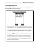
DFX-7 Ultrasonic Thickness Gauge functionality and structure. The illustrations below are snapshots of typical GRID and SEQ LOG file formats: Grid File Formats Sequential Log Formats Important Note: For the duration of this chapter, all references to GRIDS and SEQ LOGS should be considered synonymous with references to FILES. 11.2 Creating a new Grid or Sequential Log (File) Important Note: This entire section is a step by step guide to successfully create a grid or sequential log.
Dakota Ultrasonics Creating a Name Grid/Seq Log Name : Can contain a combination of up to 20 numeric, alpha, or special characters listed in the first section of this chapter. Grid Log Sequential Log 1) Press the MENU key once to activate the menu items tab. Press the MENU key multiple times to tab right, and the ESC key multiple times to tab left, until the DATA menu is highlighted and displaying the submenu items.
DFX-7 Ultrasonic Thickness Gauge Grid Log Sequential Log 4) Press the ENTER key to display the new Grid or Seq Edit Box. 5) Use the UP and DOWN arrow keys to scroll through the new Grid or Seq List Items until NAME is highlighted. 6) Press the ENTER key to activate the Alpha Edit Box. 7) Use the UP, DOWN, LEFT, & RIGHT arrow keys to highlight the appropriate alpha characters. 8) Press the ENTER key to select a character and advance to the next field of the Grid or Seq Name.
Dakota Ultrasonics 9) Use the CLR key to backspace if necessary. 10) Repeat steps 6 - 9 until the Grid or Seq Name (File Name) is completed. 11) Press the OK key to save the Grid or Seq Name and return to the Grid or Seq List Items menu, or ESC to cancel entering the Grid or Seq Name (File Name). Creating a Note Grid/Seq Log Note: Can contain a combination of up to 20 numeric, alpha, or special characters listed in the first section of this chapter.
DFX-7 Ultrasonic Thickness Gauge 3) Use the UP, DOWN, LEFT, & RIGHT arrow keys to highlight the appropriate alpha characters. 4) Press the ENTER key to select a character and advance to the next field of the Grid or Seq Note. 5) Use the CLR key to backspace if necessary. 6) Repeat steps 3 through 5 until the Grid or Seq Note is completed. 7) Press the OK key to save the Grid or Seq Note and return to the Grid or Seq List Items menu, or ESC to cancel entering the Grid or Seq Note.
Dakota Ultrasonics Sequential: The sequential file format can be viewed as a file as a single column of up to 512 possible rows (readings), and a column of corresponding identifiers associated with each individual reading. The identifier can be a combination of up to 10 numeric, alpha, or special characters listed above, while the file name can consist of a combination of up to 20 of the same character set. Note: The identifier cannot start or end with a special character.
DFX-7 Ultrasonic Thickness Gauge Grid Log Sequential Log 3) GRID LOG: Use the LEFT, & RIGHT arrow keys to scroll the Columns, and the UP, DOWN arrow keys to scroll the Rows. SEQ LOG: Use the UP, DOWN, LEFT, & RIGHT arrow keys to highlight the appropriate alpha characters. Press the ENTER key to select a character and advance to the next character field, in conjunction with using the CLR key to backspace if necessary.
Dakota Ultrasonics Grid Log Sequential Log 1) Use the UP and DOWN arrow keys to scroll through the new Grid or Seq List Items until LOWER RIGHT or END ID is highlighted. 2) Press the ENTER key to activate the Coordinate or End ID Edit Box. Grid Log Sequential Log 3) GRID LOG: Use the LEFT, & RIGHT arrow keys to scroll the Columns, and the UP, DOWN arrow keys to scroll the Rows. SEQ LOG: Use the UP, DOWN, LEFT, & RIGHT arrow keys to highlight the appropriate alpha characters.
DFX-7 Ultrasonic Thickness Gauge and advance to the next character field, in conjunction with using the CLR key to backspace if necessary. 4) Press the OK key to select the coordinate or end ID and return to the Grid or Seq List Items screen, or ESC to cancel the selection and return to the Grid or Seq List Items menu. Note: If there is not enough memory available to create the grid or sequential log, an error message box “NOT ENOUGH MEMORY“ will be displayed.
Dakota Ultrasonics Selecting the Auto Increment Direction The Auto Increment feature gives the user the ability to specify which direction to advance the cursor after storing a reading. Grid Log Sequential Log 5) Use the UP and DOWN arrow keys to scroll through the new Grid or Seq List Items until INCR. DIR or DIRECTION is highlighted. 6) Use the LEFT & RIGHT arrow keys to toggle the Increment direction NONE, NORTH, EAST, SOUTH, or WEST for a grid, or INC, DEC for a sequential log.
DFX-7 Ultrasonic Thickness Gauge Saving Graphics The DFX-7 provides the user with the ability to save a snapshot of the display screen and all the current settings of the DFX-7 with every reading, or just save the reading only. Saving the graphics might be advantageous to the user when the A/B-Scan views will be used to graphically save a picture of the scanned areas for reporting purposes. It might also come in handy when user requires backup of all the current DFX-7 parameters for each reading.
Dakota Ultrasonics Saving a Grid Once all the parameters are set, the user has the option of saving or canceling the new grid. Grid Log Sequential Log 4) Use the UP and DOWN arrow keys to scroll through the new Grid or Seq List Items until CREATE GRID or LOG? is highlighted. 5) Press the ENTER key to accept the grid or seq log parameters and activate the confirmation screen.
DFX-7 Ultrasonic Thickness Gauge Grid Log Sequential Log 6) Press the OK key to save the New Grid or Seq Log, or the ESC key to cancel the New Grid or Seq Log setup and return to the DATA menu. 7) Press the MEAS key to return to the measurement screen and begin storing readings. 11.3 Storing a reading Now that a grid or sequential log has been created, it’s time to make some measurements and store the readings.
Dakota Ultrasonics Grid Log Sequential Log 1) Press the UP, DOWN, LEFT, and RIGHT arrow keys to scroll the target cell cursor to the desired storage location. 2) Press the ENTER key to save the current reading in the highlighted cell location. It’s as simple as that! 3) Press the MEAS key to hide the GRID/SEQ View Box, or ENTER to display it as necessary. Note: Once the file is open, it will remain open until it’s closed or another file is opened by the user.
DFX-7 Ultrasonic Thickness Gauge Viewing Stored Readings & A/B Scans Grid Log Sequential Log 1) Press the MEAS key once to activate measure menu items. Press the MEAS key multiple times to move right and the ESC key multiple times to move left until the LOG cell is highlighted. 2) Press the ENTER key to display the Grid Log Box. 3) Press the UP, DOWN, LEFT, and RIGHT arrow keys to scroll the stored readings and corresponding display view.
Dakota Ultrasonics the reading. Readings stored in memory are indicated by displaying a MEM in the top left corner of the measurement screen. 4) The user may opt to clear a specific reading and save a new one at any time. Press the CLR key in the appropriate cell location to clear the reading, take a new measurement, and press the ENTER key to save the new reading. 5) Abort the Grid/Seq Log View Box by pressing the MEAS key at any time. 11.
DFX-7 Ultrasonic Thickness Gauge 3) Press the ENTER key to display the File List Box. 4) Use the UP and DOWN arrow keys to scroll through the stored Files until the target File to delete is highlighted. 5) Press the OK key to delete the File. 6) Press the MEAS key to return to the measurement screen. Deleting All Data 1) Press the MENU key once to activate the menu items tab.
Dakota Ultrasonics 2) Use the UP and DOWN arrow keys to scroll through the sub menu items until DELETE ALL DATA is highlighted. 3) Press the ENTER key to activate the confirmation screen. 4) Press the OK key to delete All Files from memory, or the ESC key to abort. 5) Press the MEAS key to return to the measurement screen.
DFX-7 Ultrasonic Thickness Gauge 11.6 Editing a Grid (File) Once a grid has been created and saved to memory, the user can edit the Comments or Increment Direction at a later time. The following procedures outline this process: Editing a Grid 1) Press the MENU key once to activate the menu items tab. Press the MENU key multiple times to tab right and the ESC key multiple times to tab left until the DATA menu is highlighted and displaying the submenu items.
Dakota Ultrasonics 5) Press the ENTER key to activate the Alpha Edit box – Only used when editing the NOTE. 6) Use the UP, DOWN, LEFT, & RIGHT arrow keys to highlight the appropriate alpha characters. 7) Press the ENTER key to select a character and advance to the next field of the Comments. 8) Use the CLR key to backspace if necessary. 9) Repeat steps 6 - 8 until the Comments are completed.
DFX-7 Ultrasonic Thickness Gauge 10) Press the UP or DOWN arrow key to highlight SAVE CHANGES, and the OK key to activate the confirmation screen. 11) Press the OK key to save the changes or the ESC key to cancel editing the file parameters. 12) Press the MEAS key to return to the measurement screen. 11.7 Changing the active File - Open The user may have transferred grid/seq templates from a PC to the DFX-7, or setup grids/seq using the DFX-7 at an earlier time.
Dakota Ultrasonics Grid Log Sequential Log 1) Press the MENU key once to activate the menu items tab. Press the MENU key multiple times to tab right and the ESC key multiple times to tab left until the DATA menu is highlighted and displaying the submenu items. 2) Use the UP and DOWN arrow keys to scroll through the sub menu items until OPEN is highlighted.
DFX-7 Ultrasonic Thickness Gauge 3) Press the ENTER key to display the Grid/Seq List Box. 4) Use the UP and DOWN arrow keys to scroll through the grids until the target grid is highlighted. 5) Press the ENTER key to activate the confirmation screen. 6) Press the OK key to load the file from memory. 7) Press the MEAS key to return to the measure screen. 11.
Dakota Ultrasonics A user might not have a current requirement to store measurements, but a file is currently open or active and needs to be closed. The following procedures outline how to close an open or active file: Closing an Active File 1) Press the MENU key once to activate the menu items tab. Press the MENU key multiple times to tab right and the ESC key multiple times to tab left until the DATA menu is highlighted and displaying the submenu items.
DFX-7 Ultrasonic Thickness Gauge 3) Press the ENTER key to close the active file. Note: Following the key press, the CLOSE text will be grayed out indicating the file has been close and is no longer active.
CHAPTER TWELVE SETUPS – CREATE, STORE, EDIT, & RECALL 12.1 Introduction to Setups Often times, users are faced with a variety of tasks and applications that are sometimes similar, but often times very different. With a standard thickness gauge, the user would have to recalibrate for each individual application respectively. With all the features of the DFX-7, the number of potential applications also increases based on ability alone.
DFX-7 Ultrasonic Thickness Gauge Opening a Setup 1) Press the MENU key once to activate the menu items tab. Press the MENU key multiple times to tab right and the ESC key multiple times to tab left until the SETUP menu is highlighted and displaying the submenu items. 2) Use the UP and DOWN arrow keys to scroll through the sub menu items until OPEN is highlighted. 3) Press the ENTER key to display the Setup List Box.
Dakota Ultrasonics 4) Use the UP and DOWN arrow keys to scroll through the setups until the target setup is highlighted. 5) Press the ENTER key to activate the confirmation screen. 6) Press the OK key to load the setup from memory. 7) Press the MEAS key to return to the measure screen. 12.3 Saving a Setup Once the DFX-7 parameters and features have be adjusted for an application, the user may elect to save these setting to a specific setup location for future use.
DFX-7 Ultrasonic Thickness Gauge Saving a Setup 1) Press the MENU key once to activate the menu items tab. Press the MENU key multiple times to tab right and the ESC key multiple times to tab left until the SETUP menu is highlighted and displaying the submenu items. 2) Use the UP and DOWN arrow keys to scroll through the sub menu items until SAVE is highlighted. 3) Press the ENTER key to display the Save Setup Parameters List Box.
Dakota Ultrasonics 5) When the parameter to edit is highlighted, press the ENTER key to activate the Alpha Edit Box. 6) Use the UP, DOWN, LEFT, and RIGHT arrow keys to scroll through the characters, the ENTER key to select characters, and the CLR key to backspace through the characters, until the Name or Note fields have been edited. 7) Press the OK key to return to the Save Setup Parameters List Box. 8) If both parameters will be edited, repeat steps 4 – 7.
DFX-7 Ultrasonic Thickness Gauge 10) Press the ENTER key to activate the Setup List Box. 11) Use the UP and DOWN arrow keys to scroll through the setups until the target location to save the Setup is highlighted. 12) Press the OK key to activate the confirmation screen. 13) Press the OK key to save the Setup, or ESC to cancel saving the Setup. 14) Finally, press the MEAS key to return to the measurement screen.
Dakota Ultrasonics 12.4 Deleting a Saved Setup This option allows a user to delete setup files that were previously saved and no longer needed. It’s a simple feature to allow the user to do a bit of “house cleaning”. Deleting a Setup 1) Press the MENU key once to activate the menu items tab. Press the MENU key multiple times to tab right and the ESC key multiple times to tab left until the SETUP menu is highlighted and displaying the submenu items.
DFX-7 Ultrasonic Thickness Gauge 3) Press the ENTER key to display the Setups List. 4) Press the UP and DOWN arrow keys to scroll to the Setup Name. 5) When the Setup Name is highlighted, press the ENTER key to display the confirmation screen. 6) Press the OK key to delete the Setup File. 7) Finally, press the MEAS key to return to the measurement screen. 12.
Dakota Ultrasonics Using the Default Setup 1) Press the MENU key once to activate the menu items tab. Press the MENU key multiple times to tab right and the ESC key multiple times to tab left until the SETUP menu is highlighted and displaying the submenu items. 2) Use the UP and DOWN arrow keys to scroll through the sub menu items until DEFAULT SETUP is highlighted. 3) Finally, press the MEAS key to return to the measurement screen.
DFX-7 Ultrasonic Thickness Gauge 12.6 Selecting a Language The DFX-7 is equipped with a language option. Currently, the only languages supported are English, Spanish, and German. The steps to select one of these languages are outlined as follows: Selecting a Language 1) Press the MENU key once to activate the menu items tab. Press the MENU key multiple times to tab right and the ESC key multiple times to tab left until the SETUP menu is highlighted and displaying the submenu items.
CHAPTER THIRTEEN USING THE UTILITY SOFTWARE 13.1 Computer System Requirements DakView will run on many different operating systems: Windows XP, Windows 2000 Professional, Windows 2000 Server, Windows 2000, Vista, Windows 7 or 8. Advanced Server operating systems running on Intel or AMD hardware. A Pentium 166MHz or faster processor with at least 32 megabytes of physical RAM is required. You should have 40 megabytes of free disk space before attempting to install DakView.
DFX-7 Ultrasonic Thickness Gauge 13.3 Using the XFER menu (DFX-7) The XFER menu of the DFX-7 will be used in conjunction with the DakView PC software. The steps below outline the procedure for accessing the XFER menu and basic operation as follows: Accessing and Using the XFER Menu 1) Press the MENU key once to activate the menu items tab. Press the MENU key multiple times to tab right, and the ESC key multiple times to tab left, until the XFER menu is highlighted and displaying the submenu items.
APPENDIX A VELOCITY TABLE Material sound velocity in/us sound velocity m/s Aluminum Beryllium Brass Bronze Cadmium Columbium Copper Glass (plate) Glycerine Gold Inconel Iron Cast Iron Lead Magnesium Mercury Molybdenum Monel Nickel Nylon Platinum Plexiglas Polystyrene PVC Quartz glass Rubber vulcanized Silver Steel (1020) Steel (4340) Steel Stainless" Teflon 0.2510 0.5080 0.1730 0.1390 0.1090 0.1940 0.1830 0.2270 0.0760 0.1280 0.2290 0.2320 0.1800 0.0850 0.2300 0.0570 0.2460 0.2110 0.2220 0.1060 0.
DFX-7 Ultrasonic Thickness Gauge Tin Titanium Tungsten Uranium Water Zinc Zirconium 0.1310 0.2400 0.2040 0.1330 0.0580 0.1660 0.
APPENDIX B SETUP LIBRARY Num Name 1 2 3 4 5 6 … Enter Custom Name … … … … … … Comment 1 168 Gn/AGC Velocity
WARRANTY INFORMATION Warranty Statement Dakota Ultrasonics warrants the DFX-7 against defects in materials and workmanship for a period of two years from receipt by the end user. Additionally, Dakota Ultrasonics warrants transducers and accessories against such defects for a period of 90 days from receipt by the end user. If Dakota Ultrasonics receives notice of such defects during the warranty period, Dakota Ultrasonics will either, at its option, repair or replace products that prove to be defective.