
User`s manual


1M60 Camera User’s Manual 14
DALSA C32-10010-01
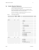
Serial Cable Source
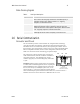
The remote interface connector, on the cameras rear panel, is
specified as a low-profile RJ-11 modular connector. The connector
is a 6-position model, but only the center four positions are
populated with contacts. It will mate with either the 4-position or 6-
position cable plugs. This type of connector typically requires
special assembly tools; complete cable assemblies are available from
suppliers such as Digi-Key:
Digi-Key
701 Brooks Ave. South
Thief River Falls, MN 56701
1-800-344-4539
cable part number:
H2643-14-ND (14 feet)
DALSA provides serial cables in 3 lengths: 10’, 20’ and 50’. Part number CL-31-00004-xx (where xx
refers to the cable length in feet).
2.7
TTL Trigger Input and Output
Connector
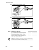
The camera uses an SMA connector (labeled TRIGGER IN) to allow the user to
provide a standard TTL signal to control camera integration and readout. The input is
high impedance (>10K) allowing the user to terminate at the SMA input as needed.
The camera has another SMA connector (TRIGGER OUT) that provides a standard
TTL output which is high whenever the camera is integrating.
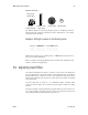
Figure 5. Trigger Timing Description
2.8
Integration Time
The minimum integration time (or shutter time) is 5 µs. As with any full frame
imager, the camera will continue to integrate during read out unless externally
shuttered or strobed.
TTL Trigger Input
Integration
1.5 us
+/- 0.5
Min. 5 µs