PANTERA 22M Camera User’s Manual Progressive Scan Monochrome Camera CA-40-22M03-00-L 20-Aug-11 www.teledynedalsa.
PANTERA 22M User’s Manual About Teledyne Technologies and Teledyne D ALSA, Inc. Teled yne Technologies is a lead ing provid er of sophisticated electronic subsystem s, instrum entation and com m unication prod ucts, engineered system s, aerospace engines, and energy and pow er generation system s. Teled yne Technologies’ operations are prim arily located in the United States, the United Kingd om and Mexico. For m ore inform ation, visit Teled yne Technologies’ w ebsite at w ww .teled yne.com .
PANTERA 22M User’s Manual 3 Contents Introduction to the PANTERA 22M Area/TDI Scan Camera ____________________________ 5 1.1 Camera Highlights ....................................................................................................................................................... 5 1.2 Image Sensor ............................................................................................................................................................... 6 1.
PANTERA 22M User’s Manual Camera Link™ Reference, Configuration and Image Construction______________________ 41 Commands and Error Handling _____________________________________________ 45 Index _______________________________________________________________ 49 Revision History ________________________________________________________ 51 Teledyne DALSA 03-032-20049-02
PANTERA 22M User’s Manual 5 1 Introduction to the PANTERA 22M Area/TDI Scan Camera 1.1 Camera Highlights Features • 4008(H ) x 5344(V) resolu tion, fu ll fram e CCD architectu re • • • • • • • • • • The PAN TERA 22M offers u p to 3.
PANTERA 22M User’s Manual Applications The PAN TERA 22M are ou tstand ing perform ers in fast, very high resolu tion ap plications. 12 bit perform ance provid es u p to 4096 d istinct gray levels—perfect for ap plications w ith large interscene light variations. The low -noise, d igitized vid eo signal also m akes the cam era an excellent choice w here low contrast im ages m u st be captu red in challenging ap plications.
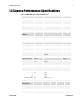
PANTERA 22M User’s Manual 7 1.3 Camera Performance Specifications Table 1: PANTERA 22M Camera Performance Specifications Camera Features Units Resolution H x V pixels 4008 x 5344 Pixel Size µm 9x9 Pixel Fill Factor % 100 Output taps Notes 4 Mechanical Interface Units Size mm 78 x 78 x 70 Weight kg 0.
PANTERA 22M User’s Manual At front plate Operating Tem p °C -10 50 Gain Range dB 0 24 Dynam ic Range dB 63 Pixel Response N on Uniform ity (PRN U) DN rm s 5 Fixed Pattern N oise (FPN ) DN rm s 3 Sat. Output Am plitud e DN 3680 3840 4000 1 DC Offset DN 80 160 240 1 >100x 1 21 12-bit @530nm Antibloom ing 2 Responsivity DN / (nJ/ cm ) Pow er Up Duration sec 10 Pow er Up Stabilization tim e m in 30 P P 19 20 Regulatory Regulatory Com pliance N one Notes: 1.
PANTERA 22M User’s Manual 9 1.4 Blemish specification PAN TERA 22M cam era inclu d es an FTF4052M CCD im age sensor, ind u strial grad e. Blem ish specification is presented below . Below table show s FTF4052M Sensor Blem ish Specifications, m axim u m nu m ber of blem ishes perm itted .
Teledyne DALSA PANTERA 22M User’s Manual 03-032-20049-02
PANTERA 22M User’s Manual 11 2 Camera Hardware Interface 2.1 Installation Overview In ord er to set u p you r cam era, you shou ld take these initial step s: This installation overview assumes you have not installed any system components yet. 1. Pow er d ow n all equ ipm ent. 2. Follow ing the m anu factu rer’s instru ctions, install the fram e grabber (if ap plicable). Be sure to observe all static precautions 3. Install any necessary im aging softw are. 4.
PANTERA 22M User’s Manual Figure 3: Camera Inputs/Outputs 2.2.1 LED Status Indicator Please refer to section 3.12 Monitoring the Cam era , page 24 for d etail. HT TH T TH 2.2.2 Camera Link Data Connector The Cam era Link interface is im plem ented as a Base Configu ration in the PAN TERA 22M cam eras. A Base Configu ration u ses 1 MDR26 connector and 1 Channel Link chip.
PANTERA 22M User’s Manual 13 Table 2: MDR26 Connector Reference Item Value Pinout BASE 1 2 3 4 5 6 7 8 9 10 11 12 13 GN D X0X1X2XclkX3SERTC+ SERTFGCC1CC2+ CC3CC4+ GN D Item Pinout Value BASE 14 15 16 17 18 19 20 21 22 23 24 25 26 GN D X0+ X1+ X2+ Xclk+ X3+ SERTCSERTFG+ CC1+ CC2CC3+ CC4GN D Notes: T *Exterior Overshield is connected to the shells of the connectors on both end s. **3M part 14X26-SZLB-XXX-0LC is a com plete cable assem bly, includ ing connectors.
PANTERA 22M User’s Manual See Ap pend ix A for the com plete Cam era Link tim ing, Teled yne DALSA Cam era Link configu ration table, and contact Teled yne DALSA Technical su p port, for the official Cam era Link d ocu m ent. Input Signals The cam era accepts an EXSYN C control inpu t throu gh the Cam era Link MDR26F connector. EXSYNC (Triggers Readout) For high speed com m u nication the CC lines of cam era link w ill be u sed .
PANTERA 22M User’s Manual 15 WARNING: It is extremely important that you apply the appropriate voltages to your camera. Incorrect voltages will damage the camera. Protect the camera with a fast-blow fuse between power supply and camera. Visit the w w w .teled yned alsa.com Web site for a list of com panies that m ake p ow er su pp lies that m eet the cam era’s requ irem ents. The com panies listed shou ld not be consid ered the only choices.
Teledyne DALSA PANTERA 22M User’s Manual 03-032-20049-02
PANTERA 22M User’s Manual 17 3 Software Interface: How to Control the Camera All cam era featu res can be controlled throu gh the serial interface. The cam era can also be u sed w ithou t the serial interface after it has been set u p correctly. This chapter explains the m ost com m only u sed and im portant com m and s, inclu d ing: 3.3 Saving and Restoring Settings 3.4 Setting Operating Mod e 3.5 Setting Exposu re Mod e and Exposu re Tim e (Area Mod e) 3.
PANTERA 22M User’s Manual • • • • • 1 stop bit N o parity N o flow control 9.6Kbps Cam era d oes not echo characters When entering commands, remember that: • • • A carriage retu rn (CR) end s each com m and . The linefeed character is ignored . The cam era w ill answ er each com m and w ith either "OK >" or "Error x: Error Message >". The ">" is alw ays the last character sent by the cam era.
PANTERA 22M User’s Manual 19 3.3 Saving and Restoring Settings The cam era provid es a nu m ber of com m and s for restoring, storing, and saving settings. • • • To restore the original factory settings, u se the com m and rfs. To save all cu rrent u ser settings to EEPROM, u se the com m and wus. The cam era w ill au tom atically restore the saved u ser setting s w hen p ow ered u p. To restore the last saved u ser settings, u se the com m and rus.
PANTERA 22M User’s Manual Mode Table5: Overview of PANTERA 22M Exposure Modes i SYNC Exposure Time 0 –External 1 –Internal -Program m able –Fram e rate is internally set to correspond w ith the program m ed exposure tim e plus read out tim e. –External –N ot program m able –Exposure tim e is set by the high pulse w id th of the iCC1 signal. For more information on the EXSYNC signal, refer to section 2.2 Input/Output Connectors and LED.
PANTERA 22M User’s Manual 21 0 Sm art ExSync (Area Mod e) 1 Fram e Sync Internal, Exposure Internal 2 Fram e Sync External, Exposure Internal N otes: To obtain the current value of the exposure m od e, use the com m and gcp. T Related Com m and s: set Exam ple: sem 1 T Mode 0: Smart EXSYNC, External Frame Rate and Exposure Time Figure5.
PANTERA 22M User’s Manual T5 Typical 27 u s FVAL start to LVAL start T6 Typical 74.22 u s LVAL length T7 Typical 28.
PANTERA 22M User’s Manual 23 Mode 2: External Frame Sync and Internal Exposure Time In this m od e, iCC1 sets the fram e rate bu t the exposu re tim e is set internally u sing the softw are com m and , set (d escribed on follow ing page).
PANTERA 22M User’s Manual 3.6 TDI Mode In TDI m od e, the follow ing events take place: Rising ed ge of iCC2 Line Sync pu lse or internal cou nter is triggering beginning of a new line N ew line starts w ith vertical transfer of one line Stop vertical transfer and start horizontal read ou t Read ou t d u m m y pixels Read ou t active lines. In parallel process d ata from active pixels. Enable LVAL for active pixels d ata.
PANTERA 22M User’s Manual 25 T5 Variable 1 us Depend ing on line rate If iCC2 (line sync) is ru nning at higher rate than the m axim u m , the signal w ill be ignored . When the cam era operates in TDI m od e, iCC3 is d riven H igh and iCC1 valu e is ignored (so iCC1 cou ld be d riven either LOW – recom m end ed , or H igh). The sensor is exposed all the tim e and the lines are read w ith the frequ ency of the iCC2. The valu e of FVAL w ill be set to LOW.
PANTERA 22M User’s Manual N otes: To read the current line rate frequency, use the com m and gcp. If you enter an invalid fram e rate or line rate, the valid range of values w ill be d isplayed. Related Com m and s: sem, ssm Exam ple: ssf 1 2780 3.8 Switching between Area and TDI mode (TDI/Area Mode) 1. TDI m od e to Area It is safe to sw itch from TDI m od e to Area m od e. 2. Area m od e to TDI m od e It is safe to sw itch d u ring exposu re tim e or id le tim e.
PANTERA 22M User’s Manual 27 3.10 Setting Baud Rate Change speed of cam era serial com m u nication port. Defau lt speed of com m u nication after p ow er-on cycle is alw ays 9600 bau d . Param eters of serial com m u nication are as follow s: Eight (8) d ata bits N o (N ) parity One (1) stop bit N o hard w are flow control To set the speed of the camera serial communication port, use the command: Syntax: sbr i Syntax Elem ents: i Baud rate.
PANTERA 22M User’s Manual 1-4 - Tap count (select single tap) i 0-1023. 0 correspond s to low gain, 1023 correspond s to high gain Related Com m and s: gag ; ugr Exam ple: sag 0 27 Update Gain Reference Com m and ugr is to u pd ate 0d B gain reference to be equ al to the cu rrent valu e of analog gain setting. It is the DN valu e cu rrently set to the vid eo processor’s gain registers that is u sed as the gain reference.
PANTERA 22M User’s Manual 29 3.12 Monitoring the Camera Note: When more than one condition is active, the LED indicates the condition with the highest priority. Error and warning states are accompanied by corresponding messages further describing the current camera status. The cam era is equ ipped w ith a red / green LED u sed to d isplay the operational statu s of the cam era. Table 6 below su m m arizes the operating states of the cam era and the correspond ing LED states.
Teledyne DALSA PANTERA 22M User’s Manual 03-032-20049-02
PANTERA 22M User’s Manual 31 4 Optical and Mechanical Considerations 4.
PANTERA 22M User’s Manual 4.2 Mounting the Camera The PAN TERA 22Mcam eras can be m ou nted via the 4 holes. 4.3 Thermal Management For any CCD cam era optim al perform ance is achieved by transferring heat aw ay from the sensor. Keeping a sensor ―cool‖ red u ces the am ou nt of d ark cu rrent generated . Dark cu rrent is the lead ing contribu tor to FPN , PRN U, d ark offset, rand om noise and other perform ance specifications, especially w hen a cam era is significantly gained (i.e. +10d b).
PANTERA 22M User’s Manual 33 5 Cleaning and Maintenance 5.1 Cleaning Electrostatic Discharge and the CCD Sensor Charge-cou pled d evice (CCD) im age sensors are m etal oxid e sem icond u ctor (MOS) d evices and are su sceptible to d am age from electrostatic d ischarge (ESD). Althou gh m any sensor pins have ESD protection circu itry, the ESD p rotection circu itry in CCDs is typically not as effective as those fou nd in stand ard CMOS circu its.
PANTERA 22M User’s Manual not ap pear to be d am aging the CCDs im m ed iately m ay cau se d am age w ith a change in environm ental cond itions. Protecting Against Dust, Oil, and Scratches The CCD w ind ow is p art of the optical path and shou ld be hand led like other optical com ponents, w ith extrem e care. Du st can obscu re pixels, p rod u cing d ark patches on the sensor response. Du st is m ost visible w hen the illu m ination is collim ated .
PANTERA 22M User’s Manual 35 5.2 Maintenance There are no u ser serviceable parts on this cam era. Please contact Teled yne DALSA for service.
Teledyne DALSA PANTERA 22M User’s Manual 03-032-20049-02
PANTERA 22M User’s Manual 37 6 Troubleshooting The inform ation in this chapter can help you solve problem s that m ay occu r d u ring the setu p of you r cam era. Rem em ber that the cam era is part of the entire acqu isition system .
PANTERA 22M User’s Manual 6.2 Troubleshooting Using the Serial Interface The follow ing com m and s can aid in d ebu gging. (The com plete com m and protocol is d escribed in Ap pend ix B.) Communications To qu ickly verify serial com m u nications send the help com m and . The h com m and retu rns the online help m enu . Verify Parameters To verify the cam era setu p, send the gcp com m and . Verify Factory Calibrated Settings To restore the cam era’s factory settings, send the rfs com m and .
PANTERA 22M User’s Manual 39 6.3 Specific Solutions No Output or Erratic Behavior If you r cam era provid es no ou tpu t or behaves erratically, it m ay be picking u p rand om noise from long cables acting as antennae. Do not attach w ires to u nu sed pins. Verify that the cam era is not receiving spu riou s inpu ts (e.g. EXSYN C, if cam era is in expo su re m od e that regu lates external signals).
PANTERA 22M User’s Manual 6.4 Product Support If there is a problem w ith you r cam era, collect the follow ing d ata abou t you r a p plication and situ ation and call you r Teled yne DALSA representative. Note: You m ay also w ant to photocopy this page to fax to Teled yne DALSA. Customer name Organization name Customer phone number fax number Complete Product Model Number (PT-21-11M04, PT-21-06M08...
PANTERA 22M User’s Manual 41 Appendix A Camera Link™ Reference, Configuration and Image Construction Cam era Link is a com m u nication interface for vision ap plications. It provid es a connectivity stand ard betw een cam eras and fram e grabbers. LVDS Technical Description Low Voltage Differential Signaling (LVDS) is a high-speed , low -pow er general-pu rpose interface stand ard . The stand ard , know n as AN SI/ TIA/ EIA -644, w as ap proved in March 1996.
PANTERA 22M User’s Manual Camera Control Signals Fou r LVDS pairs are reserved for general-pu rpose cam era control. They are d efined as cam era inpu ts and fram e grabber ou tpu ts. Cam era m anu factu rers can d efine these signals to m eet their need s for a p articu lar prod u ct.
PANTERA 22M User’s Manual 43 PANTERA 22M Interface Parameters Table 2: Frame Grabber Interface Parameters (Unverified) Item (when programmable configuration the options are separated with a | ) Im ager Dim ension <1,2 or 1| 2> Im ager Colum ns Im ager Row s Line Scan/ TDI are d efined as 1 N um ber of Im ager Taps <1,2,3…..
PANTERA 22M User’s Manual Item (when programmable configuration the options are separated with a | ) PANTERA 22M Pixel Reset Pulse Minim um Wid th 0 if not applicable Internal Pixel Reset Tim e Resolution 0 if not applicable Pixel Reset to Exsync H old time BAUD Rate <9600….
PANTERA 22M User’s Manual 45 Appendix B Commands and Error Handling This table provid es a brief overview of all of the available u ser com m and s. For a d etailed explanation of these com m and s, refer to Chapter 3. Parameters: i = integer f = float t = tap Teledyne DALSA Table: All Available CommandsTable 3Table 4 Command Syntax Parameters Description FPGA configuration store fcs Place the cam era into FPGA cod e d ow nload state.
Parameters: i = integer f = float t = tap PANTERA 22M User’s Manual Command Syntax Parameters Description set analog gain sag t i Setting analog gain to vid eo processor. 0~4, 0~1023 set gain sg t i Setting analog gain in the vid eo processor. 0~4, 0.0~24.0 set sync frequ ency ssf t i Sets the cam era’s fram e rate and line rate values. Current line rate m ay be obtained from Get_Camera_Parameters output. Sync rate inform ation is saved w ith user settings.
PANTERA 22M User’s Manual Parameters: i = integer f = float t = tap 47 Command Syntax set td i d irection scd Test pattern select tps Parameters i Description Set vid eo m od e. Available values are: 0: Top to Bottom 1: Bottom to Top Selects betw een vid eo output, test pattern 1, and test pattern 2 output. Test pattern m od e is saved w ith user settings.
Teledyne DALSA PANTERA 22M User’s Manual 03-032-20049-02
PANTERA 22M User’s Manual 49 Index 2 taps, 19, 20 setting, 23, 25 EXSYN C, 14 troubleshooting, 37 external trigger, 14 A F aperture, 7 applications, 6 features, 5 fill factor, 7 fram e rate, 7 FVAL, 41 2 B baud rate, 27 bright lines, 39 C cam era control signals, 42 Cam era Link configuration, 13, 14 connector, 13 signals, 13 clock signals, 13 com m and s d escriptions, 45 connector Cam era Link, 12 d ata, 12 pinout, 12 pow er, 14 D d ark patches, 39 d ata bus, 13 d ata rate, 7 d igital d ata, 13
PANTERA 22M User’s Manual P perform ance specifications, 7 pixel fill factor, 7 size, 7 pow er d issipation, 7 PRN U, 8 restoring, 19 saving, 19 size, 7 specifications, 7 electro-optical, 7 startup sequence, 18 STROBE, 13 troubleshooting, 38 R T rebooting, 29 resolution, 7 responsivity, 8 graph, 8 tap reconstruction, 42 Technical Sales Support, 40 tem perature, 8 test patterns generating, 38 tim ing exposure, 23, 25 troubleshooting, 37 S sensor alignm ent, 7 d raw ing, 6 serial interface, 17 sett
Revision History D ATE Revision Action Originator 23/ 05/ 2008 00 Initial Release Law son Lu o 19/ 11/ 2009 01 See d etail below Law son Lu o 08/ 19/ 2011 02 -Upd ate to cosm etic blem ish and sensor cleaning proced ure -Restored m issing labels to tim ing d iagram s. Gary Gagne D etails of the changes at version 01: 1. 2. 3. 4. 5. 6. 7. 8. 9.