
User`s manual

PANTERA 22M User’s Manual 13
Teledyne DALSA 03-032-20049-02
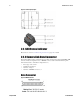
Table 2: MDR26 Connector Reference
Item
Value
Item
Value
Pinout
BASE
Pinout
BASE
1
GND
14
GND
2
X0-
15
X0+
3
X1-
16
X1+
4
X2-
17
X2+
5
Xclk-
18
Xclk+
6
X3-
19
X3+
7
SERTC+
20
SERTC-
8
SERTFG-
21
SERTFG+
9
CC1-
22
CC1+
10
CC2+
23
CC2-
11
CC3-
24
CC3+
12
CC4+
25
CC4-
13
GND
26
GND
TNotes:
*Exterior Overshield is connected to the shells of the connectors on both ends.
**3M part 14X26-SZLB-XXX-0LC is a complete cable assembly, including connectors.
Unused pairs should be terminated in 100 ohms at both ends of the cable.
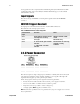
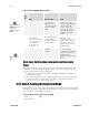
Table 3: Camera Control Configuration
Signal
Configuration
CC1
Smart EXSYNC(Area Mode)
CC2
Line Sync (TDI mode)
CC3
Area/ TDI mode
CC4
Spare
Digital Data
The camera digitizes internally to 12 bits and has a user selectable output of 8, 10, or 12
bits in LVDS format on the Camera Link connector. You can select the output using the
clm command. For details, see section3.9 Setting the Camera Link Data Mode.
Data Clocking Signals
These signals indicate when data is valid, allowing you to clock the data from the camera
to your acquisition system. These signals are part of the Camera Link configuration and
you should refer to the Teledyne DALSA Camera Link Implementation Road Map,
available with contacting Teledyne DALSA Technical support, for the standard location
of these signals:
Clocking Signal
Indicates
LVAL (high)
Outputting valid line
DVAL (high)
Valid data
STROBE (rising edge)
Valid data
FVAL (high)
Outputting valid frame
IMPORTANT:
This camera’s data
should be sampled on
the rising edge of
STROBE.