
User`s manual


14 PANTERA 22M User’s Manual
Teledyne DALSA 03-032-20049-02
See Appendix A for the complete Camera Link timing, Teledyne DALSA Camera Link
configuration table, and contact Teledyne DALSA Technical support, for the official
Camera Link document.
Input Signals
The camera accepts an EXSYNC control input through the Camera Link MDR26F
connector.
EXSYNC (Triggers Readout)
For high speed communication the CC lines of camera link will be used.
The table below shows high speed controls:
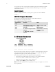
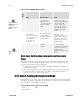
Table 4: PANTERA 22M Camera Control Configuration
Camera Link
input
Function
Note
CC1
Smart ExSync (Frame trigger
and exposure control)
Will be ignored in TDI
mode
CC2
Line sync
TDI mode only
CC3
0 - Area mode, split vertical
transfer.
1 - TDI mode, one-way
transfer
The direction of one-way
transfer is set by
software
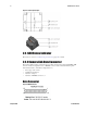
2.2.3 Power Connector
Pin
Description
Pin
Description
1
+12V
4
GND
2
+12V
5
GND
3
+12V
6
GND
The camera requires a single voltage input (+12VDC to +15VDC). The camera meets all
performance specifications using standard switching power supplies, although well-
regulated linear supplies provide optimum performance.
When setting u p the cam era’s pow er sup plies follow these guidelines:
• Protect the camera with a fast-blow fuse between power supply and camera.
• Do not use the shield on a multi-conductor cable for ground.
• Keep leads as short as possible to reduce voltage drop.
• Use high-quality linear supplies to minimize noise.
Note: Performance specifications are not guaranteed if your power supply does not meet
these requirements