
User`s manual


20 PANTERA 22M User’s Manual
Teledyne DALSA 03-032-20049-02
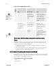
Table5: Overview of PANTERA 22M Exposure Modes
Mode
SYNC
Exposure Time
Notes
0
–External
–Not
programmable
–Exposure time is
set by the high pulse
width of the iCC1
signal.
―Sm art EXSYN C‖ Mod e:
external exposure time –
high time of external signal
is exposure time and
1/ period is frame rate.
The rising edge of iCC1
begins camera exposure.
The falling edge begins
readout.
1
–Internal
-Programmable
–Frame rate is internally
set to correspond with
the programmed
exposure time plus
readout time.
–Internal
–Programmable using
the set command
- Programmable using
the ssf command
Factory Default Mode.
Frame period is the
programmed exposure
time plus the readout time.
The frame period can be
read in this mode by using
the gcp command.
2
–External
-Programmable
with set
command
The user is responsible for
not violating timing
constraints for the EXSYNC
signal used in this mode.
The falling edge of
EXSYNC initiates the frame
transfer.
Overview: Setting Exposure mode and Exposure
Time
The cam era’s fram e rate (synchronization) can be generated internally through software
commands or input externally from a frame grabber/ host system. To select how you
want the camera’s fram e rate to be generated :
1. You must first set the camera mode using the sem command. Refer to Step One on
the following for details.
2. Then, if you are using mode 1, use the TsetT command to set the exposure time. Refer
to Step Two in 3.5.2 for details. Then use the Tssf Tto set the frame rate. Refer to HT3.7
Setting Sync Frequency (TDI and Area Mode)TH.
3.5.1 Step 1: Setting the Exposure Mode
In internal sync mode, (mode 1), the camera delivers data independent of external signals
according to the timing set internally. In external sync modes (modes 2), the camera starts
exposure after an external trigger pulse (iCC1).
To select camera’s exposure mode, use the command:
Syntax:
sem i
Syntax Elements:
i
i
Mode 1 is the factory
setting
i
For more information on
the EXSYNC signal, refer
to section 2.2
Input/Output Connectors
and LED.