
User`s manual

1
right-click
1
12
405-00026-00iNspect Express User’s Manual
68 Rev 1600; 12 July 2010
h. Click on the padlock button to lock the value for “Perfect” so it does not change if you
move or resize the tool, or change parameters.
i. Click the “Preprocess” button
to add image filtering, or feature enhancement. Adding
preprocessing may increase inspection time. Please refer to page 15.
j. Click on the “check” button
to accept changes and close the Contour Properties box.
Click the X button
to close without changes.
Using the Contour Tool
The Contour Tool looks for flashing, burr, cut or thread defects along an edge; usual-
ly a machined part. This tool can be used for other edges as well. This tool measures
deviation or change in positions, and reports the number of “failed” sections that
were greater than the allowed distance tolerance. By default, two measurements are
enabled.
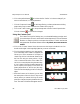
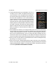
a. Click on the “Contour” button. Move the mouse over the image in the Work Area. You
should see the edges in the image highlighted as you move across them.
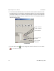
b. .Find the edge that matches your measurement.
Click on the edge, and a “rubber” line appears and
follows your cursor movement. If the edge is a
closed loop, the line is the shortest distance from
the first click and your mouse position. Right-
click to reverse the direction of the rubber line.
Left-click on a second point along the same edge.
A line is drawn following the edge, between the
two click points, and a group of “ruler lines” are
drawn perpendicular to the line and the edge.
These lines are the sampling points for finding the
edges.
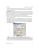
c. When the Contour tool is selected, you can drag
the center points of the ruler lines, if they are not
exactly where you wanted. Moving the center
points also changes the spacing between the ruler
lines. The small solid boxes that appear near the