
User`s manual
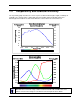


Table Of Contents
- Introduction to the Falcon XDR and HG Cameras
- Camera Hardware Interface
- Serial Interface: How to Control the Camera
- Serial Protocol Defaults
- Command Format
- 3.1 Setting Baud Rate
- 3.2 Camera Serial Command Help Screen
- 3.3 Retrieving Information About the Camera
- 3.4 First Power Up Camera Settings
- 3.5 Saving and Restoring Settings
- 3.6 Camera Output Format
- 3.7 Setting Exposure Mode, Frame Rate and Exposure Time
- 3.8 Setting a Vertical Window of Interest
- 3.9 Flat Field Correction
- 3.10 Gain Adjustments
- 3.11 Generating a Test Pattern
- Optical and Mechanical Considerations
- Troubleshooting
- Appendix A: Camera Link™ Reference, Timing, and Configuration Table
- Appendix B: Error Handling and Command List
- Appendix C: EMC Declaration
- Technical Support
- Index

Falcon XDR and HG Series Camera User's Manual DALSA
Introduction to the Falcon XDR and HG Cameras 11
Electrical Interface Units Notes
Input Voltage Volts +12V to 15V
Power Dissipation W < 3
Operating Temperature °C 0 to 50 1
Output Data Configuration Base mini-Camera Link
Output Format (# of taps) 2 Tap Interleaved (odd/even)
Mono Operating Ranges Units Notes
Data Rate MHz 2 @ 80
Random Noise DN rms 1.7 (Falcon XDR)
3.2 (Falcon HG)
7
Broadband Responsivity DN/(nJ/cm
2
) 19 (Falcon XDR)
48 (Falcon HG)
DC Offset DN 1 5
Antiblooming
>1000 x Saturation
FPN DN rms 0.9 (Falcon XDR)
4.3 (Falcon HG)
5, 7
PRNU DN rms 4.7 (Falcon XDR)
4.3 (Falcon HG)
5, 6, 7
Integral non-linearity DN < 2% 3
Color Operating Ranges Units Notes
Data Rate MHz 2 @ 80
Random Noise DN rms Red: 1.7 (Falcon XDR)
Blue: 1.7 (Falcon XDR)
Green: 1.7 (Falcon XDR)
Red: 3.5 (Falcon HG)
Blue: 3.5 (Falcon HG)
Green: 3.6 (Falcon HG)
7
Broadband Responsivity DN/(nJ/cm
2
) See Section 1.3
DC Offset DN 1 5