
User`s manual
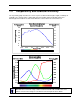


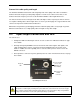
Table Of Contents
- Introduction to the Falcon XDR and HG Cameras
- Camera Hardware Interface
- Serial Interface: How to Control the Camera
- Serial Protocol Defaults
- Command Format
- 3.1 Setting Baud Rate
- 3.2 Camera Serial Command Help Screen
- 3.3 Retrieving Information About the Camera
- 3.4 First Power Up Camera Settings
- 3.5 Saving and Restoring Settings
- 3.6 Camera Output Format
- 3.7 Setting Exposure Mode, Frame Rate and Exposure Time
- 3.8 Setting a Vertical Window of Interest
- 3.9 Flat Field Correction
- 3.10 Gain Adjustments
- 3.11 Generating a Test Pattern
- Optical and Mechanical Considerations
- Troubleshooting
- Appendix A: Camera Link™ Reference, Timing, and Configuration Table
- Appendix B: Error Handling and Command List
- Appendix C: EMC Declaration
- Technical Support
- Index

DALSA Falcon XDR and HG Series Camera User's Manual
20 Camera Hardware Interface
Camera Link cable quality and length
The maximum allowable Camera Link cable length depends on the quality of the cable used and the
Camera Link strobe frequency. Cable quality degrades over time as the cable is flexed. Also, as the
Camera Link strobe frequency is increased, the maximum allowable cable length will decrease.
The Falcon cameras have been designed such that at the highest strobe frequency the Falcon cameras
are capable of driving cables 10m in length. This is to ensure system integrity since a typical Camera Link
camera can only achieve 5.6m transmission distances.
DALSA does not guarantee good imaging performance with low quality cables of any length. In general,
DALSA recommends the use of high quality cables in lengths for any cable length.
2.2 Input/Output Connectors and LED
The camera uses:
• A diagnostic LED for monitoring the camera. See the section
2.2.1 LED Status Indicator on page
21 for details.
• One high-density 26-pin SDR26 connector for Camera Link control signals, data signals, and
serial communications. Refer to section
2.2.2 Camera Link Data Connector on page 21 for
details. In addition, the PoCL capability of these cameras allows power to also be sent on the
SDR26 connectors.
• One 6-pin Hirose connector for power (optional). Refer to section
2.2.5 Power Connector on page
25 for details.
Mini-Camera Link
SDR26
Connector
Hirose Power Input
+12V to +15V
(Optional: PoCL
also available)
Diagnostic
LED
STATUS
POWER
12V-15V DC
CONTROL & DATA 1
Input/Output Connectors
WARNING: Ensure that all the correct voltages at full load are present at the camera end of the power
(irrespective of cable length) according to the pinout defined in section
2.2.5 Power Connector on page
25. A common system problem is that the voltage drop across the power cable is large enough that the
voltage at the camera does not meet the power input voltage specifications.