Spyder 3 Camera Link Camera Link Dual Line Scan Camera User’s Manual 14-Jul-08 03-032-20008-03 www.dalsa.
PRELIMINARY Spyder 3 CL User's Manual © 2008 DALSA. All information provided in this manual is believed to be accurate and reliable. No responsibility is assumed by DALSA for its use. DALSA reserves the right to make changes to this information without notice. Reproduction of this manual in whole or in part, by any means, is prohibited without prior permission having been obtained from DALSA.
Spyder 3 CL User's Manual PRELIMINARY 3 Contents 1 Introduction to the Spyder 3 CL Camera ____________________________________ 5 1.1 Camera Highlights.......................................................................................................................................................5 1.2 Camera Performance Specifications ............................................................................................................................7 1.3 Image Sensor.........................
PRELIMINARY Spyder 3 CL User's Manual 7.5 Analog and Digital Signal Processing Chain...............................................................................................................55 7.6 End-of-line Sequence ..................................................................................................................................................69 7.7 Look-Up Tables ....................................................................................................................
Spyder 3 CL User's Manual PRELIMINARY 5 1 Introduction to the Spyder 3 CL Camera 1.
PRELIMINARY Spyder 3 CL User's Manual Applications The Spyder 3 CL camera is ideal for: • FPD inspection • Pick and place • Container inspection • Wood/tile/steel inspection • 100% print inspection (lottery tickets, stamps, bank notes, paychecks) • Postal sorting • Glass bottle inspection • Industrial metrology • Food inspection • Web inspection Models The Spyder 3 CL camera is available in these models.
Spyder 3 CL User's Manual PRELIMINARY 7 1.
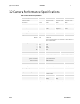
PRELIMINARY Specifications Table 3: Camera Operating Specifications Unit -10dB Min Typ Max Broadband responsivity Min Spyder 3 CL User's Manual 0dB Typ Max Min +10dB Typ Max 6528 3264 3264±16 1632±16 30 65 DN/(nJ/cm²) Dual line Single line 4k Dual line 4k Single line Random noise rms Dynamic range Dual line Single line 4k Dual and Single FPN global Uncorrected Corrected PRNU ECD Uncorrected local Uncorrected global Corrected local Corrected global PRNU ECE Uncorrected local Uncorrected glob
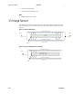
Spyder 3 CL User's Manual PRELIMINARY • Exposure mode disabled. • Unless specified, dual line mode. 9 Notes 1. PRNU measured at 50% SAT. 1.3 Image Sensor The camera uses DALSA’s dual line scan sensor. The camera can be configured to read out in either high or low sensitivity mode, tall pixel mode, and forward or reverse shift direction.
PRELIMINARY Spyder 3 CL User's Manual Sensitivity Mode and Pixel Readout The camera has the option to operate in either high sensitivity (dual line) or low sensitivity (single line) modes, or in tall pixel mode. When in high sensitivity mode, the camera uses both line scan sensors and its responsivity increases accordingly. When in low sensitivity mode, the camera uses the bottom sensor only.
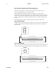
Spyder 3 CL User's Manual PRELIMINARY 11 Figure 5: Tall Pixel Mode In tall pixel mode, the camera uses a 28µm x 14µm pixel (1k and 2k) or a 20µm x 10µm pixel (4k model) and captures an image two times taller than in high or low sensitivity modes, resulting in a taller image.
PRELIMINARY Spyder 3 CL User's Manual 1.4 Responsivity Figure 7: Spyder 3 CL 1k and 2k Responsivity Spectral Responsivity. Nominal Gain 2500 High Sensitivity Mode 2250 Low Sensitivity Mode Responsivity {DN/(nJ/cm²)} 2000 1750 1500 1250 1000 750 500 250 0 400 500 600 700 800 900 1000 1100 Wavelength (nm) Figure 8: Spyder 3 CL 4k Responsivity Spectral Responsivity.
Spyder 3 CL User's Manual PRELIMINARY 13 1.
PRELIMINARY Spyder 3 CL User's Manual Figure 10: 4k Derating Curves Changes in DC offset with Integration Time (12bit, 0dB, HSM, 4K model) 4K model: Change in DC Offset vs Temperature (12bit, Integration Time 200us) 200.000 140 180.000 120 160.000 100 140.000 DN DN 80 120.000 +10dB HSM 100.000 +10dB LSM 60 80.000 40 60.000 -10dB LSM 40.000 20 20.000 0.000 0 3.3 2.0 1.0 0.5 0.3 0.2 0.1 0C 0.
Spyder 3 CL User's Manual PRELIMINARY 15 2 Setting Up the Camera 2.1 Installation Overview When installing your camera, you should take these steps: This installation overview assumes you have not installed any system components yet. 1. Power down all equipment. 2. Following the manufacturer’s instructions, install the framegrabber (if applicable). Be sure to observe all static precautions. 3. Install any necessary imaging software. 4.
PRELIMINARY Spyder 3 CL User's Manual Figure 11: Input and Output Connectors 1k and 2k models 4k model A A B Diagnostic LED B Camera Link (Base Configuration) C +12V to +15V DC C ! WARNING: It is extremely important that you apply the appropriate voltages to your camera. Incorrect voltages may damage the camera. See section 2.4 for more details. 2.
Spyder 3 CL User's Manual PRELIMINARY 17 for a list of companies that make power supplies that meet the camera’s requirements. The companies listed should not be considered the only choices. 2.4 Camera LED The camera is equipped with a red/green LED used to display the operational status of the camera. The table below summarizes the operating states of the camera and the corresponding LED states. When more than one condition is active, the LED indicates the condition with the highest priority.
PRELIMINARY Spyder 3 CL User's Manual Table 7: Camera Link Connector Pinout Base Configuration One Channel Link Chip + Camera Control + Serial Communication Camera Right Angle Channel Connector Frame Link Signal Grabber 1 1 inner shield 14 14 inner shield 2 25 X0- 15 12 X0+ 3 24 X1- 16 11 X1+ 4 23 X2- 17 10 X2+ 5 22 Xclk- 18 9 Xclk+ 6 21 X3- 19 8 X3+ 7 20 SerTC+ 20 7 SerTC- 8 19 SerTFG- 21 6 SerTFG+ 9 18 CC1- 22 5 CC1+ 10 17 CC2+ 23 4 CC2- 11
Spyder 3 CL User's Manual PRELIMINARY 19 See Appendix B for the complete DALSA Camera Link configuration table, and refer to the DALSA Web site, http://mv.dalsa.com, for the official Camera Link documents. Input Signals, Camera Link The camera accepts control inputs through the Camera Link MDR26F connector. i The camera ships in internal sync, internal programmed integration (exposure mode 7) TDI Mode. EXSYNC (Triggers Frame Readout) Frame rate can be set internally using the serial interface.
PRELIMINARY Spyder 3 CL User's Manual you should refer to the DALSA Camera Link Implementation Road Map, available at http://mv.dalsa.com, for the standard location of these signals.
Spyder 3 CL User's Manual Symbol PRELIMINARY Table 9: Spyder 3 Input and Output Definition 21 Min (ns) twSYNC The minimum low width of the EXSYNC pulse when not in SMART EXSYNC mode. twSYNC(SMART) * The minimum low width of the EXSYNC pulse when in SMART EXSYNC modes to guarantee the photosites are reset.
03-032-20008-03 PRELIMINARY Spyder 3 CL User's Manual DALSA
Spyder 3 CL User's Manual PRELIMINARY 23 3 Software Interface: How to Control the Camera All of the camera features can be controlled through the serial interface. The camera can also be used without the serial interface after it has been set up correctly. Functions available include: i This chapter outlines the more commonly used commands. See section 7.17 ASCII Commands: Reference for a list of all available commands.
PRELIMINARY • Spyder 3 CL User's Manual The camera will answer each command with either “OK >" or "Error xx: Error Message >" or “Warning xx: Warning Message >”. The ">" is used exclusively as the last character sent by the camera.
Spyder 3 CL User's Manual PRELIMINARY 25 Camera Help Screen For quick help, the camera can return all available commands and parameters through the serial interface. There are two different help screens available. One lists all of the available commands to configure camera operation. The other help screen lists all of the commands available for retrieving camera parameters (these are called “get” commands).
PRELIMINARY Spyder 3 CL User's Manual 3.2 Command Categories The following diagram categorizes and lists all of the camera’s commands. This chapter is organized by command category.
Spyder 3 CL User's Manual PRELIMINARY 27 3.3 Camera Output Format How to Configure Camera Output Using the camera link mode and pixel readout direction commands Use the camera link mode (clm) command to determine the camera’s Camera Link configuration, the number of output taps, and the bit depth. Use the pixel readout direction (smm) command to select the camera’s pixel readout direction. The following tables summarize the possible camera configurations for each of the S3-xx camera models.
PRELIMINARY Spyder 3 CL User's Manual Setting the Camera Link Mode Purpose: Sets the camera’s Camera Link configuration, the number of Camera Link taps, and the data bit depth. Refer to the tables on the previous page to determine which configurations are valid for your camera model and how this command relates to other camera configuration commands.
Spyder 3 CL User's Manual PRELIMINARY 29 Figure 19: Camera Pixel Readout Direction Example using 2k Model with Inverting Lens Table 11: Forward or Reverse Pixel Readout Camera model Readout direction S3-10-01k40 S3-20-01K40 S3-10-02K40 S3-20-02K40 S3-20-04K40 DALSA Left to Right Right to Left Left to Right Right to Left Left to Right Right to Left Left to Right Right to Left Left to Right Right to Left Command Tap 1 Tap 2 smm smm smm smm smm smm smm smm smm smm 1-1024 1024-1 1-512 1024-513 1-2048
03-032-20008-03 PRELIMINARY Spyder 3 CL User's Manual DALSA
Spyder 3 CL User's Manual PRELIMINARY 31 4 Optical, Mechanical, and Electrical Considerations 4.1 Mechanical Interface Figure 20: S3 1k and 2k Mechanical Dimensions 30.000 ± 0.050 CCDIMAGING CENTER (53.9) M42x1THREAD DEEP4.0 Units: mm (49.6) (72.0) 57.0 36.000 ± 0.050 CCDIMAGING CENTER (7.5) (9.0) PIXEL1 42.0 (60.0) M3x0.5 THREAD DEEP5.0(4X) (33.7) (19.4) 6.56 ± 0.25 TOCCD IMAGING SENSOR (11.6) (30.1) M3x0.5 THREAD DEEP5.0(4X) 6.0 (14.0) DALSA 32.
PRELIMINARY Spyder 3 CL User's Manual Figure 21: S3-20-04k40 Mechanical Dimensions 32.500 ` 0.050 CCDIMAGING CENTRE n 62.0-4.5DEEP 53.7 49.4 32.6 M3x0.5THREAD DEPTH5.0(4X) 6.0(2X) 42.500 ` 0.050 CCDIMAGINGCENTRE 85.0 70.0 78.0(2X) M3x0.5THREAD DEPTH7.0(4X) 40.2 25.9 7.5 3.5 58.0(2X) 3.5 Units: mm 65.0 14.1 6.56 ` 0.25 TOCCD IMAGING SURFACE M3x0.5THREAD DEPTH5.0(4X) 6.0(2X) 16.5 32.0 4.
Spyder 3 CL User's Manual PRELIMINARY 33 • Halogen light sources generally provide very little blue relative to infrared light (IR). • Fiber-optic light distribution systems generally transmit very little blue relative to IR. • Some light sources age; over their life span they produce less light. This aging may not be uniform—a light source may produce progressively less light in some areas of the spectrum but not others.
PRELIMINARY m= Spyder 3 CL User's Manual f′ OD These equations can be combined to give their most useful form: h′ f′ = h OD This is the governing equation for many object and image plane parameters. Example: An acquisition system has a 512 x 512 element, 10 m pixel pitch area scan camera, a lens with an effective focal length of 45mm, and requires that 100μm in the object space correspond to each pixel in the image sensor. Using the preceding equation, the object distance must be 450mm (0.450m).
Spyder 3 CL User's Manual PRELIMINARY 35 5 CCD Handling Instructions 5.1 Electrostatic Discharge and the CCD Sensor Cameras contain charge-coupled device (CCD) image sensors, which are metal oxide semiconductor (MOS) devices and are susceptible to damage from electrostatic discharge (ESD). Electrostatic charge introduced to the sensor window surface can induce charge buildup on the underside of the window that cannot be readily dissipated by the dry nitrogen gas in the sensor package cavity.
PRELIMINARY Spyder 3 CL User's Manual stored in containers where they are not properly secured and can slide against the container. Scratches diffract incident illumination. When exposed to uniform illumination, a sensor with a scratched window will normally have brighter pixels adjacent to darker pixels. The location of these pixels changes with the angle of illumination. 5.3 Cleaning the Sensor Window 1. Use compressed air to blow off loose particles.
Spyder 3 CL User's Manual PRELIMINARY 37 6 Troubleshooting 6.1 Troubleshooting The information in this chapter can help you solve problems that may occur during the setup of your camera. Remember that the camera is part of the entire acquisition system.
PRELIMINARY Spyder 3 CL User's Manual EXSYNC When the camera is received from the factory, it defaults (no external input required) to exposure mode 7 (5000 Hz line rate, internal Sync to trigger readout). After a user has saved settings, the camera powers up with the saved settings.
Spyder 3 CL User's Manual PRELIMINARY • 39 Test pattern successful— Run the svm 0 command to activate video. Then run the gl command under both dark and light conditions to retrieve a line of raw video (no digital processing). Under dark conditions, with factory settings, the analog offset value should be within the specified range (refer to the user specifications). Adjust the analog offset using the sao command. Under light conditions, you should receive a value.
PRELIMINARY Spyder 3 CL User's Manual Line Dropout, Bright Lines, or Incorrect Line Rate Verify that the frequency of the internal sync is set correctly, or when the camera is set to external sync that the EXSYNC signal supplied to the camera does not exceed the camera’s useable Line rate under the current operating conditions. Noisy Output Check your power supply voltage outputs for noise. Noise present on these lines can result in poor video quality.
Spyder 3 CL User's Manual PRELIMINARY 41 6.3 Product Support If there is a problem with your camera, collect the following data about your application and situation and call your DALSA representative. Note: You may also want to photocopy this page to fax to DALSA. Customer name Organization name Customer phone number fax number email Complete Product Model Number (e.g. S3-10-01k40-00-R...
03-032-20008-03 PRELIMINARY Spyder 3 CL User's Manual DALSA
Spyder 3 CL User's Manual PRELIMINARY 43 7 Appendix A 7.1 Spyder 3 Camera Link ASCII Commands Serial Protocol Defaults • 8 data bits • 1 stop bit • No parity • No flow control • 9.6kbps • Camera does not echo characters Command Format When entering commands, remember that: • A carriage return ends each command. • The camera will answer each command with either “OK >" or "Error xx: Error Message >" or “Warning xx: Warning Message”.
PRELIMINARY Spyder 3 CL User's Manual Setting Baud Rate Purpose: Syntax: Sets the speed in bps of the serial communication port. Syntax Elements: m sbr m Baud rate. Available baud rates are: 9600 (Default), 19200, 57600, and 115200. Notes: Example: • Power-on rate is always 9600 baud. • The rc (reset camera) command will not reset the camera to the power-on baud rate and will reboot using the last used baud rate. sbr 57600 Select Cable Purpose: Syntax: Sets the cable parameters.
Spyder 3 CL User's Manual PRELIMINARY 45 Camera ASCII Command Help For quick help, the camera can return all available commands and parameters through the serial interface. There are two different help screens available. One lists all of the available commands to configure camera operation. The other help screen lists all of the commands available for retrieving camera parameters (these are called “get” commands).
PRELIMINARY Spyder 3 CL User's Manual Example ASCII Command Help Screen (1k 2 Tap Model) Parameters i = integer f = floating point number m = member of a set s = string t = tap x = pixel column number y = pixel row number ccf ccg ccp clm cpa css dpc els epc gcm gcp gcs gcv gem get gfc gh gl gla gpc gsf gsl h lpc rc rfs roi rpc rus sag sao sbh sbr scb scd sdo sem set sfc slt smm spc srm ssb ssf ssg ssm sut svm ugr vt vv wfc wpc wus correction calibrate fpn calibrate camera gain correction calibrate p
Spyder 3 CL User's Manual PRELIMINARY 47 7.2 Sensor Output Format Sensitivity Mode Purpose: Sets the camera’s sensitivity mode. When using high sensitivity mode, the camera’s responsivity increases. High sensitivity mode permits much greater scanning speeds in low light, or allows reduced lighting levels. Syntax: ssm i Syntax Elements: i Sensitivity mode to use.
PRELIMINARY Spyder 3 CL User's Manual Setting the Camera Link Mode Purpose: Sets the camera’s Camera Link configuration, number of Camera Link taps and data bit depth. Refer to the tables on the following pages to determine which configurations are valid for your camera model and how this command relates to other camera configuration commands.
Spyder 3 CL User's Manual PRELIMINARY Related Commands: ssf, set Example: sem 3 Table 12: Spyder 3 CL Exposure Modes Programmable Line Rate Mode SYNC PRIN 49 Programmable Exposure Time Description 2 Internal Internal Yes Yes Internal frame rate and exposure time. Exposure control enabled (ECE). 3 External Internal No No Maximum exposure time. Exposure control disabled (ECD). 4 External Internal No No Smart EXSYNC. ECE.
PRELIMINARY Spyder 3 CL User's Manual Mode 3: External Trigger with Maximum Exposure Line rate is set by the period of the external trigger pulses. The falling edge of the external trigger marks the beginning of the exposure. Example 2: Line Rate is set by External Trigger Pulses.
Spyder 3 CL User's Manual PRELIMINARY 51 Mode 6: External Line Rate and Internally Programmable Exposure Time Figure 24: EXSYNC controls Line Period with Internally controlled Exposure Time Line Period Programmable Period Using set Command Line Period Readou t Programmable Period Using set command Readou t EXSYNC CR=Charge Reset Mode 7: Internally Programmable Line Rate, Maximum Exposure Time In this mode, the line rate is set internally with a maximum exposure time.
PRELIMINARY i Applies to Modes 2 and 7 Spyder 3 CL User's Manual Setting the Line Rate Purpose: Sets the camera’s line rate in Hz. Camera must be operating in exposure mode 2 or 7. Syntax: ssf f Syntax Elements: i Desired line rate in Hz. Allowable values are: 1k 1 tap: 300-36000 Hz 1k 2 tap: 300-68000 Hz 2k 1 tap: 300-18500 Hz 2k 2 tap: 300-36000 Hz 4k 2 tap: 300-18500 Hz Notes: i Applies to Modes 2 and 8 • To read the current line frequency, use the command gcp or get ssf.
Spyder 3 CL User's Manual PRELIMINARY Notes: S3-20-01K40 S3-20-02K40 S3-20-04k-40 Example: 53 smm 0 = 1-512 (tap 1) or 513-1024 (tap 2) smm 1 = 1024-513 (tap 1) or 512-1 (tap 2) smm 0 = 1-1024 (tap 1) or 1025-2048 (tap 2) smm 1 = 2048-1025 (tap 1) or 1024-1 (tap 2) smm 0 = 1-2048 (tap 1) or 2049-4096 (tap 2) smm 1 = 4096-2049 (tap 1) or 2048-1 (tap 2) smm 1 Setting the Readout Mode See also, the Clearing Dark Current section in Appendix A for more information on this mode.
PRELIMINARY Spyder 3 CL User's Manual 7.4 Data Processing Setting a Region of Interest (ROI) Purpose: Sets the pixel range used to collect the end-of-line statistics and sets the region of pixels used in the ccg, gl, gla, ccf, and ccp commands. In most applications, the field of view exceeds the required object size and these extraneous areas should be ignored. It is recommended that you set the region of interest a few pixels inside the actual useable image.
Spyder 3 CL User's Manual PRELIMINARY 55 7.5 Analog and Digital Signal Processing Chain Processing Chain Overview and Description The following diagram shows a simplified block diagram of the camera’s analog and digital processing chain. The analog processing chain begins with an analog gain adjustment, followed by an analog offset adjustment. These adjustments are applied to the video analog signal prior to its digitization by an A/D converter.
PRELIMINARY Spyder 3 CL User's Manual Digital Processing To optimize camera performance, digital signal processing should be completed after any analog adjustments. 1. Fixed pattern noise (FPN) calibration (calculated using the ccf command) is used to subtract away individual pixel dark current. 2.
Spyder 3 CL User's Manual DALSA PRELIMINARY Example: sag 0 5.
PRELIMINARY Spyder 3 CL User's Manual Calibrating Camera Gain Purpose: Instead of manually setting the analog gain to a specific value, the camera can determine appropriate gain values. This command calculates and sets the analog gain according to the algorithm determined by the first parameter. Syntax: ccg i t i Syntax Elements: i Calibration algorithm to use. 1 = This algorithm adjusts analog gain so that 8% to 13% of tap region of interest (ROI) pixels are above the specified target value.
Spyder 3 CL User's Manual PRELIMINARY 59 Setting Analog Offset Purpose: Sets the analog offset. The analog offset should be set so that it is at least 3 times the rms noise value at the current gain. DALSA configures the analog offset for the noise at the maximum specified gain and as a result you should not need to adjust the analog offset. Syntax: sao t i Syntax Elements: t Tap selection. Use 0 for all taps or 1 to 2 for individual tap selection if you are using the two tap model.
PRELIMINARY Spyder 3 CL User's Manual PRNU( pixel) = PRNU correction coefficient for this pixel FPN( pixel ) = FPN correction coefficient for this pixel Background Subtract = background subtract value System Gain = digital gain value The algorithm is performed in two steps. The fixed offset (FPN) is determined first by performing a calibration without any light.
Spyder 3 CL User's Manual PRELIMINARY 61 Set up the camera operating environment (i.e. line rate, exposure, offset, gain, etc.) Set the calibration sample size using the command css. It is recommended that you use the default setting. Set the region of interest to include all of the image’s pixels of importance using the command roi x1 y1 x2 y2. You can use the default if you want to calibrate all pixels. Perform FPN calculation Perform PRNU calculation 1. Stop all light from entering the camera.
PRELIMINARY Spyder 3 CL User's Manual Digital Signal Processing To optimize camera performance, digital signal processing should be completed after any analog adjustments. FPN Correction Performing FPN Correction Syntax: Performs FPN correction and eliminates FPN noise by removing individual pixel dark current. Syntax: ccf Notes: • Perform all analog and digital adjustments before performing FPN correction. • Perform FPN correction before PRNU correction.
Spyder 3 CL User's Manual PRELIMINARY 63 Setting Digital Offset Purpose: Sets the digital offset. Digital offset is set to zero when you perform FPN correction (ccf command). If you are unable to perform FPN correction, you can partially remove FPN by adjusting the digital offset. Syntax: sdo t i Syntax Elements: t Tap selection. Allowable range is 1 to 2 depending on camera model, or 0 for all taps.
PRELIMINARY Spyder 3 CL User's Manual PRNU Correction Performing PRNU to a user entered value Purpose: Performs PRNU calibration to user entered value and eliminates the difference in responsivity between the most and least sensitive pixel, creating a uniform response to light. Using this command, you must provide a calibration target. Executing these algorithms causes the ssb command to be set to 0 (no background subtraction) and the ssg command to 4096 (unity digital gain).
Spyder 3 CL User's Manual PRELIMINARY 65 for use only when FPN is negligible and FPN coefficients are set to zero. Since this algorithm adjusts the analog gain, it also affects FPN. If FPN is calibrated prior to running this algorithm, FPN will be observable in dark conditions and an incorrect FPN value will be used during PRNU calibration resulting in incorrect PRNU coefficients.
PRELIMINARY Spyder 3 CL User's Manual cpa i i i • Perform all analog adjustments before calibrating PRNU. • This command performs the same function as the cpp command but forces you to enter a target value. • Calibrate FPN before calibrating PRNU. If you are not performing FPN calibration then issue the rpc (reset pixel coefficients) command and set the sdo (set digital offset) value so that the output is near zero under dark.
Spyder 3 CL User's Manual PRELIMINARY Notes: • 67 When subtracting a digital value from the digital video signal the output can no longer reach its maximum. Use the ssg command to correct for this where: ssg value = max output value max output value ‐ ssb value See the following section for details on the ssg command. Related Commands: ssg Example ssb 0 25 Setting Digital System Gain Purpose: Improves signal output swing after a background subtract.
PRELIMINARY Spyder 3 CL User's Manual Returning Calibration Results and Errors Returning All Pixel Coefficients Purpose: Returns all the current pixel coefficients in the order FPN, PRNU, FPN, PRNU… for the range specified by x1 and x2. The camera also returns the pixel number with every fifth coefficient. Syntax: dpc x1 x2 Syntax Elements: x1 Start pixel to display in a range from 1 to sensor pixel count. x2 End pixel to display in a range from x1 to sensor pixel count.
Spyder 3 CL User's Manual PRELIMINARY 69 Purpose: Enables and disables FPN and PRNU coefficients. Syntax: epc i i Syntax Elements: i FPN coefficients. 0 = FPN coefficients disabled 1 = FPN coefficients enabled i PRNU coefficients. 0 = PRNU coefficients disabled 1 = PRNU coefficients enabled Example: epc 0 1 7.
PRELIMINARY Location Value 9 Pixels above threshold (7…0) 10 Pixels above threshold (15…8) 11 Pixels below threshold (7…0) 12 Pixels below threshold (15…8) 13 Differential line sum (7..0) 14 Differential line sum (15…8) 15 Differential line sum (23…16) 16 Differential line sum (31…24) Spyder 3 CL User's Manual Description Monitor these values (either above or below threshold) and adjust camera digital gain and background subtract to maximize scene contrast.
Spyder 3 CL User's Manual PRELIMINARY 71 7.7 Look-Up Tables Note: This information only applies to the 4k model camera. The flat field corrections FPN and PRNU assume a linear response to the amount of light by the sensor, output node, analog amplifier, and analog to digital converter. To correct any non-linearity in this system of components a Look-Up Table (LUT) has been implemented in the FPGA for each tap immediately after the ADC.
PRELIMINARY Notes: Spyder 3 CL User's Manual Coefficients must be created first with the cil command. Setting saved with the wfs and wus commands. Example: Write Input LUT Purpose: Syntax: Syntax Elements: Example: Notes: Saves current values of input LUT that are in FPGA SDRAM to Flash memory or a PC file. wil wil 0 = Factory set 1 to 4 = User sets Input LUT is loaded by LIL, and automatically at power-up. LUT use is enabled or disabled with the EIL command.
Spyder 3 CL User's Manual PRELIMINARY 73 7.8 Saving and Restoring Settings For each camera operating mode (high sensitivity forward direction, high sensitivity reverse direction, low sensitivity, or tall pixel), the camera has distinct factory settings, current settings, and user settings. In addition, there is one set of factory pre-calibrated pixel coefficients and up to four sets of user created pixel coefficients for each operating mode.
PRELIMINARY Spyder 3 CL User's Manual 7.9 Saving and Restoring PRNU and FPN Coefficients Saving the Current PRNU Coefficients Purpose: Saves the current PRNU coefficients. You can save up to four sets of pixel coefficients Syntax: wpc i Syntax Elements: i PRNU coefficients set to save. 1 = Coefficient set one 2 = Coefficient set two 3 = Coefficient set three 4 = Coefficient set four Example: wpc 2 Saving the Current FPN Coefficients Purpose: Saves the current FPN coefficients.
Spyder 3 CL User's Manual PRELIMINARY Syntax: rpc Notes: The digital offset is not reset. 75 Rebooting the Camera The command rc reboots the camera. The camera starts up with the last saved settings and the baud rate used before reboot. Previously saved pixel coefficients are also restored. 7.10 Diagnostics Generating a Test Pattern DALSA Purpose: Generates a test pattern to aid in system debugging. The test patterns are useful for verifying camera timing and connections.
03-032-20008-03 PRELIMINARY svm smm 2 1 svm smm 2 0 svm smm 2 1 svm smm 1 0 Spyder 3 CL User's Manual 8 bit test pattern 2 tap model: 12 bit test pattern 1 tap model: DALSA
Spyder 3 CL User's Manual PRELIMINARY svm smm 1 1 svm smm 2 1 77 8 bit test pattern t tap model: 7.11 Returning Video Information The camera’s microcontroller has the ability to read video data. This functionality can be used to verify camera operation and to perform basic testing without having to connect the camera to a frame grabber. This information is also used for collecting line statistics for calibrating the camera.
PRELIMINARY Spyder 3 CL User's Manual Pixel start number. Must be less than the pixel end number in a range from 1 to sensor resolution. x2 Pixel end number. Must be greater than the pixel start number in a range from 2 to sensor resolution. Notes: • If x2 ≤ x1 then x2 is forced to be x1. • Values returned are in 12-bit DN.
Spyder 3 CL User's Manual PRELIMINARY 79 7.12 Temperature Measurement The temperature of the camera can be determined by using the vt command. This command will return the internal chip case temperature in degrees Celsius. For proper operation, this value should not exceed 75°C. Note: If the camera reaches 75°C, the camera will shutdown and the LED will flash red. If this occurs, the camera must be rebooted using the command, rc or can be powered down manually.
PRELIMINARY Spyder 3 CL User's Manual 7.15 Returning the LED Status Purpose: Syntax: Returns the status of the camera’s LED. gsl The camera returns one of the following values: 1 = red (loss of functionality) 2 = green (camera is operating correctly) 5 = flashing green (camera is performing a function) 6 = flashing red (fatal error) Notes: • Refer to section 2.4 Camera LED for more information on the camera LED 7.
Spyder 3 CL User's Manual DALSA PRELIMINARY Mirroring Mode 0, left to right Readout Mode Off Cable Parameter 200 Exposure Mode: 2 SYNC Frequency: 5000 Hz Exposure Time: 200 uSec CCD Direction: internal/forward Horizontal Binning: 1 Video Mode: video Region of Interest: (1,1) to (1024, 1) End-Of-Line Sequence: on FFC Coefficient Set: 0 81 Tap readout direction: left to right, or right to left. Set with the smm command. Current readout mode status. Set using the srm command.
03-032-20008-03 PRELIMINARY FPN Coefficients: off PRNU Coefficients: off Number of Line Samples: 1024 Upper Threshold 3600 Lower Threshold 400 Analog Gain (dB): 0.0 0.0 Analog Gain Reference(dB): 0.0 0.0 Total Analog Gain (dB): 5.5 5.5 Spyder 3 CL User's Manual section 7.9 Saving and Restoring PRNU and FPN Coefficients for details. States whether FPN coefficients are on or off. Set with the epc command. Refer to section 7.5 Analog and Digital Signal Processing Chain for details.
Spyder 3 CL User's Manual PRELIMINARY Analog Offset: 70 70 Digital Offset: 0 0 Background Subtract: 0 System Gain (DN): 4096 4096 0 83 Analog offset settings set with the sao command. See section 7.5 Analog and Digital Signal Processing Chain for details. Digital offset settings set with the sdo command. See section 7.5 Analog and Digital Signal Processing Chain for details. Background subtract settings set with the ssb command. See section 7.
PRELIMINARY Syntax Parameters Description get dil t a a Displays LUT values: t = Tap dependent: 0 for all. 1 and 2 for individual. a1 = Start LUT address. In a range from 0 to 1023. a2 = Stop LUT address, a1 < a2 get dpc x1 x2 Returns pixel coefficients without formatting. Returns LUTs status. 0: Off 1: On Returns whether the end-of-line statistics are turned off or on.
Spyder 3 CL User's Manual PRELIMINARY Syntax Parameters Description Returns whether user settings have been saved. 0 = No user settings saved 1 = User settings have been saved get rus get sag t Returns the analog gain in dB for the tap indicated t = Tap value. 0 for all taps or 1 to 2 for individual tap selection. get sao t Returns the analog offset for the tap indicated. t = 0 for all taps or 1 to 2 for individual tap selection. get sbh Returns the horizontal binning factor.
PRELIMINARY Syntax Parameters get srm get ssb t Description Returns the readout mode: 0 = Auto. 1 = Dark current clear. 2 = Immediate readout. Does not clear dark current. Returns the current background subtract value. t = Tap value. 0 for all taps or 1 to 2 for individual tap selection depending on camera model. Returns the current line/frame rate in Hz. get ssf get ssg Spyder 3 CL User's Manual t Returns the current digital gain setting.
Spyder 3 CL User's Manual PRELIMINARY Table 15: Command Quick Reference Mnemonic Syntax Parameters: t = tap id i = integer value f = float m = member of a set s = string x = pixel column number y = pixel row number DALSA Parameters 87 Description correction calibrate fpn ccf calculate camera gain ccg correction calibrate prnu ccp Performs PRNU calibration and eliminates the difference in responsivity between the most and least sensitive pixel creating a uniform response to light.
PRELIMINARY Spyder 3 CL User's Manual Mnemonic Syntax Parameters Description calculate PRNU algorithm cpa i i Performs PRNU calibration according to the selected algorithm. The first parameter is the algorithm where i is: 1 = This algorithm first adjusts each tap’s analog gain so that 8-13% of pixels within a tap are above the value specified in the target value parameter. PRNU calibration then occurs using the peak pixel in the region of interest.
Spyder 3 CL User's Manual DALSA PRELIMINARY 89 Mnemonic Syntax Parameters Description display pixel coeffs dpc x1 x2 Displays the pixel coefficients in the order FPN, PRNU, FPN, PRNU, … x1 = Pixel start number x2= Pixel end number in a range from 1 to 1024 or 2048 enable input LUT eil i end of line sequence els i Enable input LUT, where: 0: Off 1: On Sets the end-of-line sequence: 0: Off 1: On enable pixel coefficients epc i i get camera model gcm Reads the camera model number.
03-032-20008-03 PRELIMINARY Spyder 3 CL User's Manual Mnemonic Syntax Parameters Description get line average gla x x Read the average of line samples. x = Pixel start number x = Pixel end number in a range from 1 to sensor pixel count. get prnu coeff gpc x Read the PRNU coefficient. x = pixel number to read in a range from 1 – sensor pixel count. get signal frequency gsf i Reads the requested Camera Link control frequency.
Spyder 3 CL User's Manual DALSA PRELIMINARY Parameters 91 Mnemonic Syntax Description restore user settings rus set analog gain sag t f Sets the analog gain in dB. t = tap selection, either 1 or 2 depending on camera model, or 0 for all taps. f= gain value specified from –10 to +10 set analog offset sao t i Sets the analog offset. t = tap selection, either 1 or 2 depending on camera model, or 0 for all taps. i= Offset value in a range from 0 to 255 (12-bit LSB).
03-032-20008-03 PRELIMINARY Spyder 3 CL User's Manual Mnemonic Syntax Parameters Description set exposure mode sem m Sets the exposure mode: 2 = Internal SYNC, internal PRIN, programmable line rate and exposure time using commands ssf and set 3 = External SYNC, internal PRIN, maximum exposure time 4 = Smart EXSYNC 5 = External SYNC and PRIN 6 = External SYNC, internal PRIN, programmable exposure time 7 = Internal programmable SYNC, maximum exposure time. Factory setting.
Spyder 3 CL User's Manual DALSA PRELIMINARY 93 Mnemonic Syntax Parameters Description set subtract background ssb t i Subtract the input value from the output signal. t = Tap value. 0 for all taps or 1 to number of camera taps for individual tap selection. i = Subtracted value in a range from 0 to 4095. set sync frequency ssf i Set the frame rate to a value from 300Hz to 36000Hz (2k model) or 300Hz to 68000Hz (1k model). Value rounded up/down as required.
PRELIMINARY Spyder 3 CL User's Manual Mnemonic Syntax Parameters Description write PRNU coeffs wpc i Write all current PRNU coefficients to non-volatile memory, where i is: 1 = PRNU coefficient set one 2 = PRNU coefficient set two 3 = PRNU coefficient set three 4 = PRNU coefficient set four write user settings wus Write all of the user settings to nonvolatile memory. 7.18 Error Handling The following table lists warning and error messages and provides a description and possible cause.
Spyder 3 CL User's Manual DALSA PRELIMINARY 95 Message Description Error 04: Incorrect parameter value> This response returned for · Alpha received for numeric or vice versa · Not an element of the set of possible values. E.g., Baud Rate · Outside the range limit Error 05: Command unavailable in this mode> Command is valid at this level of access, but not effective. Eg line rate when in smart Exsync mode Error 06: Timeout> Command not completed in time.
PRELIMINARY Spyder 3 CL User's Manual 7.19 Clearing Dark Current Gate Dark Current Clear Note: This feature is not available for the S3-20-04k40 camera model. Image sensors accumulate dark current while they wait for a trigger signal. If the readout is not triggered in a reasonable amount of time, then this dark current accumulation may increase to an excessive amount. The result of this happening will be that the first row, and possibly additional rows (frames), of the image will be corrupt.
Spyder 3 CL User's Manual PRELIMINARY 97 S3-10-02k40 7.05KHz 8.52KHz S3-20-02k40 13.6KHz 16.4KHz S3-20-04k40 7.05KHz 8.52KHz Immediate read out mode (default, srm 2) In this mode the image is read out, including accumulated dark current, immediately following the trigger or the EXSYNC falling edge. There are no line rate limitations other than the amount of gate dark current that can be tolerated at low line rates.
PRELIMINARY Spyder 3 CL User's Manual Auto Mode (srm 0) Note: This feature is not available for the S3-20-04k40 camera model. In this mode the line rate from the camera will automatically cause a switch between the gate dark current clear mode and non gate dark current clear mode. The frequency of when this mode switchover occurs depends on the camera model.
Spyder 3 CL User's Manual PRELIMINARY 99 Dark Current Dump to Immediate Readout: Multi-Line Artifacts. SRM 0, Auto Mode. Time Period Operating Region Refer to Figure 29. Operating Mode T0 Dark Current Dump state T1 Immediate Readout state SRM 0, Auto Mode. Time Period Operating Region Refer to Figure 29. Operating Mode T0 Immediate Readout state T1 Dark Current Dump state T2 Immediate Readout state SRM 2, Immediate Readout Mode. Operating Region Time Period Refer to Figure 29.
PRELIMINARY Spyder 3 CL User's Manual Dark Current Dump to Immediate Readout (TINT > #) F DUMP F IMMEDIATE EXSYNC T DUMP T INT T VERT_TRANS LVAL Valid Dark Current Dump to Immediate Readout: Multi-Line Artifacts SRM 0, Auto Mode. Time Period Operating Region Refer to Figure 29. Operating Mode T0 Dark Current Dump state T1 Immediate Readout state SRM 0, Auto Mode. Time Period Operating Region Refer to Figure 29.
Spyder 3 CL User's Manual PRELIMINARY 101 Dark Current Dump to Immediate Readout (TINT < #) F DUMP F > DUMP (MAX) EXSYNC T DUMP T INT T VERT_TRANS LVAL Valid Dark Current Dump to Immediate Readout (TINT > #) F DUMP >F DUMP (MAX) EXSYNC T DUMP T INT T VERT_TRANS LVAL Valid DALSA 03-032-20008-03
PRELIMINARY Spyder 3 CL User's Manual Immediate Readout to Dark Current Dump: Hysteresis Artifacts SRM 0, Auto Mode. Time Period Operating Region Refer to Figure 29. Operating Mode T0 Immediate Readout state T1 Dark Current Dump state SRM 0, Auto Mode. Time Period Operating Region Refer to Figure 29.
Spyder 3 CL User's Manual PRELIMINARY 103 Setting the Readout Mode Purpose: Use this command to clear out dark current charge in the vertical transfer gates immediately before the sensor is read out. Syntax: srm Syntax Elements: i 0: Auto. Clears dark current below ~ 45% of the maximum line rate. (1k and 2k camera models only.) 1: Dark current clear. Always clears dark. Reduces the maximum line rate. (1k and 2k camera models only.) 2: Immediate readout. Does not clear dark current. (Default mode.
03-032-20008-03 PRELIMINARY Spyder 3 CL User's Manual DALSA
Spyder 3 CL User's Manual PRELIMINARY 105 8 Appendix B 8.1 Camera Link™ Reference, Timing, and Configuration Table Camera Link is a communication interface for vision applications. It provides a connectivity standard between cameras and frame grabbers. A standard cable connection will reduce manufacturers’ support time and greatly reduce the level of complexity and time needed for customers to successfully integrate high speed cameras with frame grabbers.
PRELIMINARY Spyder 3 CL User's Manual • LVAL—Line Valid (LVAL) is defined HIGH for valid pixels. • DVAL—Data Valid (DVAL) is defined HIGH when data is valid. • Spare— A spare has been defined for future use. All four enable signals must be provided by the camera on each Channel Link chip. All unused data bits must be tied to a known value by the camera. For more information on image data bit allocations, refer to the official Camera Link specification located at http://mv.dalsa.com.
Spyder 3 CL User's Manual PRELIMINARY 107 Power Power will not be provided on the Camera Link connector. The camera will receive power through a separate cable. Camera manufacturers will define their own power connector, current, and voltage requirements. 8.2 Camera Link Bit Definitions BASE Configuratio n Mode T0 Port A Bits 0 thru 7 Port B Bits 0 thru 7 Port C Bits 0 thru 7 Mode 0 1 Tap 8 bit Tap 1 LSB..Bit 7 xxxxxxx xxxxxxx Mode 1 1 Tap n bit Where n=10,12 Tap 1 LSB..
PRELIMINARY Spyder 3 CL User's Manual S3-x0-0xk40 Interface Parameters (PRELIMINARY) Table 21: Framegrabber Interface Parameters Item (when S3-10-01k40 S3-20-01k40 programmable configuration the options are separated with a | ) Imager Dimension or 1|2> S3-20-02k40 S3-20-04k-40 1 1 1 1 1 Imager Columns 1024 1024 2048 2048 4096 Imager Rows Line Scan/TDI are defined as 1 1 1 1 1 1 Number of CCD Taps <1,2,3…..
Spyder 3 CL User's Manual PRELIMINARY 109 Item (when programmable configuration the options are separated with a | ) S3-10-01k40 S3-20-01k40 S3-10-02k40 S3-20-02k40 S3-20-04k-40 Tap Reconstruction In some configurations the reconstruction may change. C0 is the default output format and must be listed. Output configurations that don’t conform are listed separately. Horizontal mirroring is supported.
PRELIMINARY Spyder 3 CL User's Manual Item (when programmable configuration the options are separated with a | ) S3-10-01k40 S3-20-01k40 S3-10-02k40 S3-20-02k40 S3-20-04k-40 Row Binning Factor <1,2,3 or 1|2|3> 1 1 1 1 1 Column Binning Factor <1,2,3 or 1|2|3> 1| 2 1| 2 1| 2 1| 2 1| 2 Pretrigger Pixels <0,1,2…or 0..15> 0 0 0 0 0 Pretrigger Lines <0,1,2.. or 0..15> 0 0 0 0 0 Frame Time Minimum 27.78 14.7 54.05 27.78 54.
Spyder 3 CL User's Manual PRELIMINARY 111 9 Appendix C 9.1 EMC Declaration of Conformity We, DALSA 605 McMurray Rd.
03-032-20008-03 PRELIMINARY Spyder 3 CL User's Manual DALSA
Spyder 3 CL User's Manual PRELIMINARY 113 10 Appendix D 10.1 Revision History DALSA Revision Number Change Description 00 Preliminary release. 01 -Revised CCD Shift Direction section. The get scd 3 command added to the list of get commands, page 83. The command scd 3: externally controlled/reverse direction. -Responsivity, random noise, SEE,, and NEE specifications revised. Previous specifications cited 8 bit numbers, not the correct 12 bit. Page 7. -Revised responsivity graph added, page 12.
03-032-20008-03 PRELIMINARY Spyder 3 CL User's Manual DALSA
Spyder 3 CL User's Manual PRELIMINARY 115 11 Index A D analog gain, 56, 58, 59 offset, 59 processing, 55 applications, 6 dark calibration.
PRELIMINARY correction, 62 framegrabber parameters, 108 FVAL, 20, 105 G gain, 5, 58 analog, 56 calibrating, 58 digital, 67, 71 reference, 59 H halogen light sources, 33 help, 25, 45 Hirose connector, 16 hot mirror, 33 I illumination, 32 incorrect line rate, 40 input/output, 15 inputs (user bus), 19 installation, 15 interface electrical, 7 mechanical, 7 optical, 7, 32 parameters, 108 L LED, 17 lens modeling, 33 light calibration.
Spyder 3 CL User's Manual PRELIMINARY S saving coefficients, 74 sensitivity setting, 47 sensor, 9 cleaning, 35 serial communication reference, 105 serial interface, 23 defaults, 23, 43 SerTC, 106 SerTFG, 106 settings factory, 25 restoring, 73 returning, 80, 83 saving, 73 shielded cables compliance, 34 statistics, 77 STROBE, 20 subtracting background, 66 sync frequency, 79 T 117 readout direction, 28 reconstruction, 107 Technical Sales Support, 41 temperature measurement, 79 test patterns, 75 test patte