Dan Dugan Sound Design Model E Automatic Mixing Controller User Guide Release Date: July 2007 Version: 1.
Important Safety Instructions and Warnings The Model E’s circuitry is made in the USA and meets applicable national safety standards. Standards Compliance The third-party power supply provided with this product has been certified to comply with UL. Safety Instructions 1. Read these instructions. 2. Keep these instructions. 3. Heed all warnings. 4. Follow all instructions. 5. Do not use this apparatus near water. 6.
Warranty Statement Warranty: One year parts and labor Dan Dugan Sound Design warrants that Model E hardware will be free from defects in components and workmanship for a period of 12 months from the date of invoice. During the warranty period, Dan Dugan Sound Design will cover the cost of all parts and labor to remedy the defect, or replace products which prove to be defective.
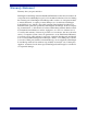
Dugan Model E User Guide Table of Contents Chapter 1: Introduction ...................................................................................................7 1.1 Conventions...............................................................................................7 1.2 Introduction to the Model E ......................................................................7 1.3 Remote Control and Software ...................................................................
Dugan Model E User Guide Chapter 5: Web Control Panel ...................................................................................25 5.1 Software Installation................................................................................25 5.2 Operation .................................................................................................28 5.2.1 Auto Mix Weight ......................................................................29 5.2.2 Logic Functions...........................
Dugan Model E User Guide Chapter 1: Introduction 1.1 Conventions We will use: 1.2 • activate to mean toggling on a button (LED lit). • de-activate to mean toggling off a button (LED not lit). • select to mean pressing a button repeatedly until the desired LED is lit. Introduction to the Model E The Model E Automatic Mixing Controller helps professional audio mixers handle multiple live mics without having to continually ride their individual faders.
Dugan Model E User Guide Introduction The Model E has many other features that dramatically improve the performance of live mixing with multiple mics: 1.
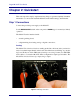
Dugan Model E User Guide Chapter 2: Quickstart This section provides step-by-step instructions to help you get started quickly. It includes information to connect and install the Model E, make initial settings, and link units. Step 1 Connections Connect the provided power supply to the Model E. Set the NORM-SLAVE switch on the rear panel to NORM (up) for normal (not linked) operation.
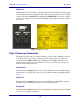
Dugan Model E User Guide Quickstart Digital I/O The Model E may be connected to a digital mixing board with ADAT connections that transmit eight channels on each digital audio optical cable. Connect the console ADAT output to the Model E LINK IN, and the Model E LINK OUT to the board’s ADAT input. On the mixing board, insert the ADAT inputs and outputs on each mic channel, post-fader. Figure 2-2 Digital connection Step 2 Power-up Commnads The Model E can execute six commands during power-up.
Dugan Model E User Guide Quickstart Step 3 Linking Multiple Units All linked units must be in analog audio I/O mode and use analog connections to the board because linking requires the digital I/O connectors. Up to eight Model Es (64 channels) can be linked into a single system that maintains the gain of one mic from the room no matter how many mics are connected. One unit must be the master and the others slaves.
Dugan Model E User Guide Quickstart Figure 2-4 Setting console preamp gain If there is insufficient gain to keep the level LEDs lit green when no one is talking, set the rear panel LEVEL switch to -10. Sufficient ambient sound level at the input is about -50 dBu in +4 mode and -62 dBu in -10 mode. The Model E does not limit, compress, or control levels. It performs just one critical function: cuing multiple mics.
Dugan Model E User Guide Chapter 3: Installation Units shipped to the USA include a 120 VAC power supply. Contact the factory if you require a different power supply. The section Section 3.1 Bench Tests Before Installation is intended for experienced technicians to test the Model E prior to installation. Those without test equipment can begin in Audio Wiring on page 14. In either case, we recommend placing the Model E in a convenient place in the mixer’s line of sight. Rack ears can be removed.
Dugan Model E User Guide 3.1 Installation Bench Tests Before Installation The Dugan Speech System can be tested with the following procedure: 1. Connect two different oscillators to inputs 1 and 2. 2. Set both to 1 kHz frequency and 0 dBu level (or -20 dBFS in digital). 3. Fine-tune the frequency of one oscillator so that the Model E gain indicators bounce up and down at about 2 Hz (1000/1002 Hz). 4. Adjust the oscillator levels so that the gain displays are equal. 5.
Dugan Model E User Guide Installation Insert This is the normal way to connect the Model E using a mic-level signal. Patch the audio channels in the insert loop (send-return) of each console input strip. Check the insert jack wiring on your mixing board. If they are 1/4-in TRS jacks (wired tip = send, ring = return), use TRS-TRS insert cables to connect the Model E. Other configurations require special cables. The Model E is wired as follows: tip = input, ring = output.
Dugan Model E User Guide Installation Figure 3-4 Insert post-fader for Speech System On your digital mixer’s patch configuration screen, patch the ADAT port channels as post-fader inserts. 3.3 Setting Levels 3.3.1 Analog Program levels from -20 to +4 dBm are within the acceptable range; 0 dBm is optimal. The level lights are green for normal operation levels and flash red at the overload point.
Dugan Model E User Guide 3.3.2 Installation Digital Adjust the console input gain trimmers so that talking signal levels at the sends are between -20 and 0 dBFS, and room noise at the sends is higher than -75 dBFS. Console input gains should be high enough so the level lights stay green all the time, but do not turn red on peaks. 3.4 Power-up Commands The Model E can execute one of six commands during each power-up.
Dugan Model E User Guide Installation Table 3-1 Display of IP Addresses on Gain LEDs 1 2 3 4 5 6 7 8 Value 0 0 0 0 0 0 0 0 8 X 0 X X 0 0 0 0 4 X 0 0 0 0 0 0 0 2 0 0 X 0 0 0 0 0 1 0 0 0 0 0 0 0 X C 0 A 8 0 0 0 1 hex address address 192 168 0 1 Digital I/O Hold the channel 3 bypass button down to switch the input and output to the ADAT link connectors.
Dugan Model E User Guide 3.5 Installation Linking Multiple Model E units are linked in a ring so they operate as one system. Two standard optical audio cables (i.e., ADAT lightpipe or Toslink) are required to link two mixers. Note that using the digital I/O prohibits linking because there is only one set of connectors. NOTE: This is different from the way the Models D and D-1 are linked. Set one Model E to be the master by setting its rear panel NORM-SLAVE switch to the NORM (up) position.
Dugan Model E User Guide Installation 20
Dugan Model E User Guide Chapter 4: Operation 4.1 How it Works The Dugan Model E Automatic Mixing Controller uses the Dugan Speech System™, a patented and trademarked automatic mixing function. The Dugan Speech System distributes the gain of one open microphone over the entire system, maintaining a natural one-mic ambience. It is essential to distinguish this behavior from the annoying fluctuation of levels and uneven ambience in a conventional gating system.
Dugan Model E User Guide 4.2 Operation Settings Figure 4-2 1. Put all the live mic channels in automatic mixing mode by deactivating bypass and mute. 2. Activate the mute buttons for all unused channels. 3. Using a normal speaking voice, adjust the console input trim controls to the highest possible gain without clipping. The input gain to the Model E should be high enough keep the level LED lit green during silences.
Dugan Model E User Guide Operation Figure 4-3 During ambience with 4 mics, auto mix gain displays should hover around -6 dB Figure 4-4 During ambience with 8 mics, auto mix gain displays should hover around -9 dB TIP: 4.3 To eliminate unwanted noise in the mix, use the gain displays to locate the offending channel and activate its mute button. Pre-fader Insert The Dugan Speech System works best if patched post-fader. If your console allows this, skip this section.
Dugan Model E User Guide Operation Controller Control System Gain Control Console Microphone Input Insert Point A EQ Insert Point B Fader Insert Point C Mix Bus Figure 4-5 Insert points on most analog mixers are at point B To properly mute a channel: • Leave the console faders up, adjust levels while people are talking, and mute a mic by pressing the Dugan’s mute mode button. Enable the mic when needed by putting it back into auto mode.
Dugan Model E User Guide Chapter 5: Web Control Panel Figure 5-1 Web Control Panel 5.1 Software Installation The Model E contains an internal web server that downloads two Java applets into the user’s web browser. Download the latest Java Runtime Environment (JRE) from: http://java.sun.com/javase/downloads/index.jsp. The Model E applet requires JRE version 5 or later. Insert the software CD supplied with the Model E or download the collection of Model E files from: http://www.dandugan.
Dugan Model E User Guide Web Control Panel The Model E’s factory default IP address is 192.168.0.1. Note that the subnet is 0, which keeps the Model E from interfering with other network devices, but also prevents it from being recognized by most networks. The method to change the IP address depends on whether the Model E is connected directly to a computer or to a network router/switch. In either case, drag Index.htm to a web browser.
Dugan Model E User Guide Web Control Panel If the unit is connected directly to the computer: 1. Choose an IP address that matches your computer’s first three groups of digits and a last group that is one integer higher. 2. Click Change. If the unit is connected to a switch or router: 1. Select the Use DHCP checkbox. 2. Click Change. The unit reboots with the new IP address and appears in the left pane. If the unit does not appear in the left pane, click Refresh.
Dugan Model E User Guide 5.2 Web Control Panel Operation Figure 5-4 Web Control Panel The web control panel provides controls not available when using the Model E as a standalone device (See Chapter 4: Operation for standalone operation): • The auto mix weight controls set the relative sensitivity of the automatic mix for the channels in use. • The manual, auto, and mute buttons transition each channel smoothly between modes.
Dugan Model E User Guide Web Control Panel The control panel in the right pane mimics all the Speech System controls of a Model D-2 or D-3. Since the Model E has no Music System algorithm, those controls do not appear. The Model E does not have groups. If linked with a D-series mixer, the Model E’s channels are assigned to group a. Since the Model E’s front panel has no man button, Manual mode is displayed as full gain. The channels and the unit itself can be named by entering text in the windows.
Dugan Model E User Guide Web Control Panel It is important to understand that the Speech System works by detecting the ratios of the levels between channels, not their absolute levels.
Dugan Model E User Guide Web Control Panel For optimal performance, balance the auto mix weight controls so the channel gains display approximately equally when no one is talking. If there is ongoing noise near one mic (i.e., computer fan or air vent), suppress it by reducing that channel’s auto mix weight. See Chapter 4: Operation for further details on automatic mixing operation. 5.2.
Dugan Model E User Guide Web Control Panel To set channel presets: 1. Click the channel preset button until the LED displays the desired setting. 2. For all unused channels, click the preset button until mute is selected. The preset indicators should mirror your normal working combination of input modes. The normal condition can then be restored by pressing the master preset button. This is also the state in which the system powers itself up.
Dugan Model E User Guide Chapter 6: ASCII Remote Control 6.1 Installation The rear panel Ethernet jack can be connected directly to a computer with a crossover cable, or to a network router or switch with a straight cable. 6.2 ASCII Remote Control Commands 6.2.1 Introduction The Model E responds to ASCII command strings to control the unit remotely with third-party control systems. Every control available on the Remote Control Panel can be accessed with command strings. To test ASCII commands: 1.
Dugan Model E User Guide ASCII Remote Control The second format requires two extra bytes. The first byte is 0xFE (254 in decimal) and is the only 8th-bit-set number accepted by the Model E. The second extra byte is the check-sum byte that is the lower 7 bits of the 8-bit sum of all the bytes from 0xFE to , inclusive. The two formats may be mixed. Whenever 0xFE is detected, the E automatically switches to the extended format.
Dugan Model E User Guide ASCII Remote Control Channel Bypass Queries or sets the channel’s Bypass status (0 = No Bypass; 1 = Bypass). Query Example Sent Reply Meaning BP 2 Is channel 2 Bypassed? BP 2, 0 No Bypass on channel 2 Set Example Meaning Sent BP 2, 1 Set channel 2 to Bypass Reply BP 2, 1 Channel 2 is Bypassed Channel Mode Use this command to query and set the mode of the given channel.
Dugan Model E User Guide ASCII Remote Control Channel Name This command queries or sets the channel’s name (15 character maximum). Query Example Sent Reply Channel Meaning CN 2 2 What is channel 2’s name? CN 2, speaker1 2 Channel 2’s name = speaker1 Set Example Channel Meaning Sent CN 2, speaker1 2 Set channel 2’s name = speaker1 Reply CN 2, speaker1 2 Channel 2’s name = speaker1 Channel Override Use this command to query and set a given channel’s override status.
Dugan Model E User Guide ASCII Remote Control Channel Preset This command queries and sets the channel’s current preset mode.
Dugan Model E User Guide ASCII Remote Control Unit Name This command queries or sets the unit’s name (15 character maximum). Query Example Sent Reply Meaning NA What is the unit’s name? NA Dugan2 Unit’s name = Dugan2 Set Example Meaning Sent NA Dugan2 Set unit’s name = Dugan2 Reply NA Dugan2 Channel 2’s name = Dugan2 System Mute This command queries and sets the system (master) mute that affects all channels.
Dugan Model E User Guide ASCII Remote Control System Override This command queries and sets the system override status.
Dugan Model E User Guide ASCII Remote Control DHCP Mode Queries or sets the DHCP mode (1 = use DHCP, 0 = do not use DHCP). Query Example Sent Meaning DH Reply Is DHCP mode active? DH 1 DHCP enabled Set Example Meaning Sent DH 0 Do not use DHCP mode Reply DH 0 DHCP disabled IP Address This command sets or queries the IP Address (in dot format) of the Model E. Query Example Meaning Sent IP What is the Model E’s current IP address? Reply IP 192.168.1.2 IP address = 192.168.1.
Dugan Model E User Guide ASCII Remote Control Ethernet Gateway This command sets or queries the Ethernet Gateway IP address (in dot format). Query Sent Example Meaning GW What is the Ethernet Gateway’s IP address? Reply GW 192.168.1.2 Ethernet Gateway’s IP address = 192.168.1.2 Set Example Meaning Sent IP 192.168.1.2 Set the IP address to 192.168.1.2 Reply IP 192.168.1.2 IP address is 192.168.1.2 Network Mask This command sets or queries the Network Mask (in dot format) of the Model E.
Dugan Model E User Guide ASCII Remote Control Headroom Returns the current headroom state. HR 0 = -10 dBU and HR 1 = +4 dBU. Example Meaning Sent HR What is the headroom state? Reply HR 1 Headroom = +4 dBU Master or Slave Mode Queries the master/slave mode of the unit (0 = Slave, 1 = Master). Example Meaning Sent MM What is the master/slave mode of the Model E? Reply MM 1 Model E = Master mode Version This command returns the microcontroller and DSP firmware versions.
Dugan Model E User Guide Chapter 7: Firmware Updates Program updates and other improvements, installed while the Model E is connected to a host computer, can be found at: http://www.dandugan.com/downloads OR http://tech.groups.yahoo.com/group/duganusers/files/ Three types of Model E program update files are identified by their name extensions: • microcontroller firmware – .hex • DSP firmware – .ldr • Web Control Panel – .wdl To update your Model E: 1.
Dugan Model E User Guide Firmware Updates DSP Firmware (.ldr file) 8. Hold down the Control and Shift keys and click the Reset button on the screen. A prompt appears asking for a new DSP firmware file. 9. Find and double-click on the new .ldr file. If the unit does not reboot automatically, cycle the power off and on. 10. Click the Refresh button to see the new version number below the Dugan logo. Web Control Panel (.wdl file) 11.
Dugan Model E User Guide Chapter 8: Specifications Specifications Audio Inputs unbalanced, 6 KOhm, -22 to +4 dBu nominal level, +21 dBu maximum Audio Outputs unbalanced, 100-Ohm source, drives a 600-Ohm load, +21 dBu maximum Output Noise less than -91 dBu (A-weighted); 112 dBA dynamic range Alternative Digital I/O ADAT optical, 48 KHz/24 bit, (8 channels only; units cannot be linked when using digital I/O) Frequency Response 10 Hz to 22 KHz, +0/-1 dB Crosstalk -81 dB @ 20 KHz Distortion less
Dugan Model E User Guide Specifications 46
Dugan Model E User Guide Chapter 9: Connector Pinouts Table 9-1 Analog I/O jacks Signal Tip Input Ring Output Sleeve Ground Table 9-2 10 BASE T (Ethernet, TCP/IP) Pin Signal 1 T2 2 T1 3 R2 4 n/c 5 n/c 6 R1 7 n/c 8 n/c 47