
Specifications


Installation Instructions
PREPARE WATER LINE
ADJUST DOOR BALANCE
4
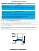
6"
5"
5"
4"
Cabinet Face
Shut-off
Valve
4"
2" From Floor
19" From Wall
2"
From
Cabinet
1-1/2" Dia.
Hole
Hot
Figure 9
Increase
Spring
Te n s i o n
Decrease
Spring
Te n s i o n
Figure 10
The water line should enter from the left side of the cabinet.
(See Fig. 9) Drill 1-1/2” diameter hole to allow water line to
pass through the cabinet. Drill a secondary 1/2” diameter hole
to allow the electrical power line to pass through the cabinet.
IMPORTANT: THE WATER LINE AND ELECTRICAL
IMPORTANT: THE WATER LINE AND ELECTRICAL
LINE SHOULD NOT SHARE THE SAME HOLE/OPENING.
LINE SHOULD NOT SHARE THE SAME HOLE/OPENING.
The dishwasher must be installed on the “hot” water line, using
no less than 3/8” O.D. copper tubing, or alternatively 3/8”
flexible braid (high pressure, high temperature) hose
engineered/designed specifically for dishwasher installations.
(this type of hose is available at most local hardware stores)
It is also recommended to install a shut-off valve in an accessible
location (i.e. under the sink) between the incoming hot water
supply and the dishwasher connection.
The dishwasher water “inlet valve” is located at the lower front
center of the dishwasher behind the kick-plate. (See Fig. 11)
Incoming water temperature should be at least 120ºF (49ºC) and
the water pressure should be between 20~120 psi.
The balance of the door is set for moderate opening/closing tension.
If you feel it is not adjusted to your satisfaction, it can be adjusted
by increasing/decreasing the tension of the door springs. (See Fig. 10)
Remove the spring holding pin and reposition to higher/lower hole
opening.
The higher hole openings will increase door tension.
The lower hole openings will decrease door tension.
WARNING: Always exercise extreme caution when making
adjustments to the door and door springs and make sure the door is
fully closed before attempting any such adjustments.
REMOVE KICK-PLATE
Figure 11
Before you can make the water/electrical connections to the dishwasher,
the "kick-plate" must first be removed.
To remove the kick-plate, lay the dishwasher on it's back. Remove 4
screws (2 on each side) from the underside of the kick-plate. (See Fig.11)
It is not necessary to reinstall these screws once removed, as the
kick-plate simply snaps into position when reinstalled.
To remove kick-plate, insert fingers under one side and pull upward,
this may require applying some force (pressure) before the kick-plate
releases. Repeat the same procedure on the opposite side.
Kick-Plate
Screws
Kick-Plate
Water Inlet
Valv e
Electrical
Connection Box