
Install Instructions

Index
Applications
The Series 30 is a multi-purpose thermostatic mixing valve
designed for ease of installation and a wide variety of uses.
The TMV offers accurate temperature control via a self-regulating
thermostat. The valves are designed to control temperature of
Domestic Hot Water (DHW), Hydronic Radiant Space Heating,
Heat Pump, and Solar Systems for central mixing applications.
Series 30 MR offer the following features:
•
Anti-scald function* (see below).
• Listed to meet ASSE 1017 requirements (applies to 85–120°F
and 95–140°F only).
• Purpose: Mixing function.
• Temperature Ranges: 70–110°F (20–43°C),
85–120°F (29–49°C), or 95–140°F (35–60°C).
• Maximum working pressure: 150psi (10 bar).
• Maximum hot water inlet temperature: 194°F (90°C).
• Maximum pressure difference between hot and cold supply:
20% to max. 44psi (3 bar).
• Minimum flow requirement: 0.5USgpm (113.5l/hr).
• Designed for long-life and easy maintenance.
• Minimal outlet temperature fluctuation.
VERY IMPORTANT!
To the Installer:
These installation and maintenance instructions
must be reviewed by all installers and by the owners
of the building or property where the device will
be installed.
* The Series 30 is designed to respond to a failure of the cold
water supply by a complete closing of the hot water supply port
before the outlet temperature exceeds the setting by 18°F (10°C).
NOTE: To ensure that the anti-scald function works properly, the
pressure difference between inlets and outlet should not exceed 72
psi (5 bar), otherwise minor leakage could occur.
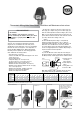
Setting
The Series 30 MR temperature setting is accomplished by
adjusting the setting wheel between 1 and 6 to obtain the
required mixed water temperature. For quick setting refer to the
table below. Series 30 MR valves are not factory calibrated.
For accurate setting, measure the mixed water temperature once
hot and cold supply temperatures are stabilized. Adjust setting as
required to obtain the desired temperature.
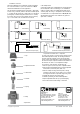
Installation
To protect the TMV from excessive heat, and avoid voiding the
warranty, the tailpieces must be soldered before attaching them to
the TMV (see below). Gaskets supplied must be installed as shown.
NOTE: When installing a TMV on plumbing systems using CPVC
piping, always follow the pipe manufacturer’s instructions.
Adjust temperature setting
between 1–6.
Mount label on cap to seal
valve. Space is provided on the
label to indicate measured
outlet temperature, date and
signature of installer.
1. Position union nut
over tailpiece
before soldering.
2. Solder tailpiece to
tubing.
3. Insert gasket in nut.
4. Connect to TMV.
Gasket
Coppertubing
TMV
Solder joint
Installation and Maintenance InstructionsThermostatic Mixing Valve Series 30 MR
© Copyright. All rights reserved.
Over time the temperature setting
may have to be adjusted due to
scaling or dirt deposited in the
valve.
F
F
F
F
–
+
F
F
F
F
F
F
–
+
F
F
F
F
F
F
–
+
F
F
F
F
F
F
–
+
F
F
F
F
F
F
–
+
F
F
Note: Table is based on 50°F cold water and no difference between hot and cold water supply pressures. For other cold water temperatures correct the mixed
temperature by 1°F for every 10°F from 50°F, up or down.
Push pin to remove cap. Remove cap. Replace cap.
120°F 67 74 81 87 94 109 80 90 97 102 107 115 95 106 115 119 120 120 86 100 112 118 120 120
140°F 68 75 82 90 97 113 81 91 99 104 109 117 97 108 117 126 133 140 87 100 114 127 136 140
160°F 69 76 84 92 100 118 82 93 100 106 112 118 99 109 118 127 135 145 88 101 117 129 144 152
180°F 70 77 86 95 102 122 82 95 102 108 114 120 100 111 120 129 135 149 89 102 119 134 148 160
Hot water 70–110°F 85–120°F 95–140°F 85–160°F
Temperature 1 2 3 4 5 6 1 2 3 4 5 6 1 2 3 4 5 6 1 2 3 4 5 6