Installation and Service instructions DHP-H DHP-L DHP-A DHP-AL DHP-C VMBMA602
If these instructions are not followed during installation, operation and maintenance, Danfoss AS’s liability according to the applicable warranty is not binding. © 2008 Copyright Danfoss AS. Danfoss AS retains the right to make changes to components and specifications without prior notice.
Contents Installation instructions.................... 4 Service instructions........................... 40 1 Important information/Safety regulations . . . . . . . . . . . . . . . . . . . 4 12 The heat pump . . . . . . . . . . . . . . . . . . . . . . . . . . . . . . . . . . . . . . . . . . . 40 1.1 1.2 1.3 1.4 Refrigerant . . . . . . . . . . . . . . . . . . . . . . . . . . . . . . . . . . . . . . . . . . . . . . . . . . . . . . . . Electrical connection . . . . . . . . . . . . . . . . . . . . . . . .
Installation instructions 1 Important information/Safety regulations The heat pump must be installed by authorised installation ⚠⚠engineers and the installation must follow the applicable local rules and regulations as well as these installation instructions.
1.4 Control and safety devices To ensure a correct function of the heat pump there are a number of control and safety devices. The figure below shows the heat pump’s three liquid circuits with respective safety function. nection to the drain and visibly flow into this in a frost-free environment. Compressor The compressor is equipped with a thermal overload relay which protects the compressor from over current.
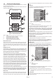
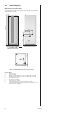
2 Heat pump information NOTE! The illustrations are schematic. Deviations from the ⚠⚠original are present. 2.1 DHP-H 1845 (±10) Dimensions and connections 110 440 300 2 528 1 40±10 455 596 610 4 9 6 7 8 80 3 5 Figure 4: DHP-H and connections. The brine pipes can be connected on either the left or right-hand sides of the heat pump.
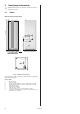
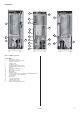
Components 4 14 15 5 6 1 16 7 8 19 9 2 10 3 18 8 11 17 13 21 20 12 Left view Front view Right view Figure 5: DHP-H, components.
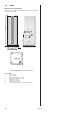
2.2 DHP-H Opti Pro Dimensions and connections 1845 (±10) The brine pipes can be connected on either the left or right-hand sides of the heat pump. 110 440 300 2 528 1 40±10 455 596 610 4 9 6 7 8 80 3 5 Figure 6: DHP-H, DHP-H Opti Pro and connections.
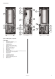
Components 4 14 5 15 6 1 16 7 19 9 2 3 8 22 18 10 11 17 21 20 23 12 13 Left view Front view Right view Figure 7: DHP-H Opti Pro, components.
2.3 DHP-C Dimensions and connections 1845 (±10) The brine pipes can be connected on either the left or right-hand sides of the heat pump. 110 440 300 1 528 2 40±10 455 596 610 4 6 7 5 8 80 3 Figure 8: DHP-C, Dimensions and connections.
Components 7 17 18 8 1 9 19 10 11 2 5 3 22 12 13 6 4 21 14 20 15 23 24 16 Left view Front view Right view Figure 9: DHP-C, components.
2.4 DHP-L, DHP-L Opti Dimensions and connections The brine pipes can be connected on either the left or right-hand sides of the heat pump. 110 1538 (±10) 440 300 2 528 1 40±10 455 596 690 5 610 4 3 7 80 6 Figure 10: DHP-L, DHP-L Opti, Dimensions and connections.
Components 1 11 2 13 5 16 6 3 4 12 8 7 10 15 14 18 17 9 Left view Front view Right view Figure 11: DHP-L, DHP-L Opti components.
2.5 DHP-A, DHP-A Opti 2 Dimensions and connections The brine pipes can be connected on either the left or right-hand sides of the heat pump. 1175 405 2 441 1205 342 630 1 1 300 910 Figure 13: Outdoor unit, Dimensions and connections.
Components 14 5 2 15 6 1 7 16 8 17 13 3 24 4 9 19 11 21 22 10 20 18 23 12 Left view Front view Right view Figure 15: DHP-A, DHP-A Opti, components.
2.6 DHP-AL, DHP-AL Opti Dimensions and connections The brine lines can be connected on either the left or right-hand sides of the heat pump. Water heater 1538 (±10) Heat pump 2 16 14 15 17 7 596 13 12 6 5 10 11 1 4 3 9 8 40±10 40±10 455 690 455 690 2 Figure 16: DHP-AL, DHP-AL Opti dimensions and connections.
Components 1 2 3 4 5 13 6 7 9 17 8 16 10 14 18 15 11 12 Left view Front view Figure 19: DHP-AL, DHP-AL Opti components.
2.7 Package contents Delivery check 1. Check that there is no transport damage. The heat pump is packaged in cardboard. 2. Check that the delivery contains the following components. Sizes 4kW - 10kW: Part no. Quantity Name 086U2369 1 Safety valve 9 bar 1/2" 086U2701 086U0896 1 1 Outdoor sensor Kimsafe 200 035 Safety valve 1,5 bar 1/2" 086U2824 1 Expansion and bleed tank without valve 086U0026 5 Rubber collar hole 22-32mm 086U6033 2 Flex.
2.8 Heat pump control panel 2.10 The heat pump control panel consists of a display, four control buttons and an indicator. ROOM 20°C (20°C) NO DEMAND HEAT OPERAT. AUTO The symbols in the display are only examples. Certain symbols cannot be displayed at the same time.
2.12 Space requirement, outdoor unit, DHPA, -AL • To ensure the function of the outdoor unit, there must be at least 300 mm of space behind and 1500 mm at the front. • For maintenance work there must be approximately 300 mm of space at the sides of the outdoor unit. Drilling holes for brine pipes NOTE! Ensure that the holes for the insert pipes are posi⚠⚠tioned so that there is room for the other installations. ⚠⚠ NOTE! The brine pipes shall have separate lead-ins.
4 Separating the heat pump Does not apply to DHP-A, -AL. If there is a shortage of space when transporting the heat pump to the installation location it may be necessary to separate the heat pump unit and the water heater. The following instruction describes how the heat pump is separated to transport the separate parts more easily. NOTE! Do not lift heavy equipment alone, always use two ⚠⚠people for heavy lifting. -Top sensor (325, 326) 11. Unscrew the electrical panel’s screws. 12.
5 5.1 Unpacking and installation 2. Tilt the front cover outwards. 3. Lift the front cover upwards to remove it from the heat pump. Setting up 5.3 • The heat pump has feet that can be adjusted 20 mm to compensate for irregularities in the surface on which it is sitting. If the surface is so irregular that the feet cannot compensate for it, the installation engineer must remedy this.
8. Screw the outdoor unit onto the stand. Use 4 x M6x20 screws. It may be necessary to push and pull the stand slightly in order to get the screw holes to align. NOTE! When filling the brine system the outdoor unit must ⚠⚠be bled using the bleed screws on the connecting pipes inside the side covers. We recommend that you return to this instruction after the brine system has been filled. 9. Reinstall the side panels. Assembling the front cover 10.
6 Piping installation DHP-H, -C, -A, DHP-H Opti Pro, connection diagram VL system NOTE! To prevent leaks, ensure that there are no stresses in ⚠⚠the connecting pipes! 1 2 NOTE! It is important that the heating system is completely ⚠⚠bled after installation. 3 NOTE! The connection diagrams show general piping ⚠⚠arrangements. It is imperative that piping installation is carried out in accordance with applicable local rules and regulations.
DHP-L, connection diagram VL system DHP-AL, connection diagram VL system 1 2 4 11 12 13 14 5 15 16 6 7 18 3 17 13 7 Figure 45: General connection diagram DHP-AL. Figure 43: General connection diagram DHP-L.
6.2 D system, DHP-L 6.3 With a DHP-L in a D system, the heat pump can produce both heating and hot water with the compressor and an external auxiliary heater (oil boiler, electric boiler, district heating or similar) that is located after the exchange valve replaces the integrated auxiliary heater to produce heat. The cables for the integrated auxiliary heater must be disconnected, which means that the heat pump cannot carry out peak heat charging (legionella function).
6.6 DHP-AL, connection diagram VLD 23 20 22 10 All pipes should be routed in such a way that vibrations cannot be transmitted from the heat pump through the piping and out into the building. This also applies to the expansion pipe. To avoid the transmission of vibrations, we recommend that flexible hoses are used for the supply line and return line on both the heating system and brine system sides. Flexible hoses are available to purchase from Danfoss AS.
6.7 Filling the water heater and heating system 1. Fill the water heater with cold water by opening the filler valve (10) which is located on the valve pipe. 2. Bleed by opening one of the hot water taps. 3. Then fill the water heater coil and the heating system with water through the filling valve (12) to a pressure of approx. 1 bar. 6.8 1. 2. 3. 4. 5. Bleeding the heating system Open all radiator valves fully. Bleed all radiators. Refill the heating system to a pressure of approximately 1 bar.
Figure 56: Recommended distance between trunking on the wall and trunking on the heat pump is 300mm. 7.1 7.4 Connect power supply, 400V 3N NOTE! The power cable may only be connected to the termi⚠⚠nal block intended for this purpose. No other terminal blocks may be used! 7.2 • The sensor must be positioned at least 1 m from openings in the walls that emit hot air. • If the sensor cable is connected through a pipe, the pipe must be sealed so that the sensor is not affected by outgoing air.
7.5 Resetting to system D or VLD For a description of the different system solutions, see section Piping installation. The heat pump has VL as factory setting. For D system, DHP-L: If D system is selected, the cables for the internal auxiliary heater must be disconnected according to the figure below. Connect the external auxiliary heater according to the connection diagram below.
8 8.1 Brine installation Heat sources Bedrock heat To use rock as the heat source one or more boreholes is/are drilled and the brine hose is lowered into it/them. The hole is filled with water and a fitting with a weight is fastened to the hose before it is lowered. Figure 60: Ground water as heat source.
8.2 Information collector pipe Local rules and regulations related to type of collector must ⚠⚠be followed. Borehole collector: Fully welded plastic pipe collector (PEM PN 6.3) according to the applicable local and national regulations with factory manufactured return bend. Ground collector: Fully welded plastic pipe collector (PEM PN 10) according to the applicable local and national regulations.
8.5 Connection diagram DHP-A: The position lists show the components and parts included in the delivery in italics. If the outdoor unit is installed higher than the heat pump the expansion outlet must be used together with a pressure tank. DHP-C: If the outdoor unit is installed at the same level or lower than the heat pump, the accompanying plastic vessel can be used. The upper part of the outdoor unit must then not exceed the fluid level in the vessel.
DHP-AL: If the outdoor unit is installed higher than the heat pump the expansion outlet must be used together with a pressure tank. If the outdoor unit is installed at the same level or lower than the heat pump, the accompanying plastic vessel can be used. The upper part of the outdoor unit must then not exceed the fluid level in the vessel. Heat pump Water heater Figure 69: Connection diagram for brine pipes.
Filler cock When the filler cock is installed on the return line, remember to turn the strainer cover upwards in order to minimise the amount of air that gets into the brine system when cleaning the filter. Figure 71: Filler cock. Position 3 4 5 6 7 Name Shut-off valve Shut-off valve Shut-off valve Strainer Shut-off valve 8.8 Bleeding the brine circuit ⚠⚠ NOTE! When topping up, the brine pump must be running. 1.
9 Installing accessories/additional functions 9.1 9.2 Room temperature sensor The room temperature sensor has a temperature sensor that provides a further value that the control computer can use when calculating the supply temperature. The influence of the room sensor in the calculation can be set in the menu HEAT CURVE-> ROOM FACTOR. Default setting for ROOM FACTOR is 2 but can be adjusted from 0 (no impact) to 4 (large impact).
10 Start up Activate MANUAL TEST NOTE! Read the safety instructions! The installation may only be commissioned if the heating ⚠⚠system, water heater and brine system have been filled and bled. Otherwise the circulation pumps may be damaged. 1. Ensure that the main circuit breaker is on. 2. Select operating mode , in the menu INFORMATION -> OPERAT.-> 3. Open the SERVICE menu by holding in for five seconds. 4. Set the value for MANUAL TEST to 2.
10.3 Commissioning Starting circulation pumps manually If any of the circulation pumps do not start, it may need to be helped as follows: ⚠⚠ NOTE! Hot! Figure 76: The pressure pipe should get hot during operation. 20. Check that: • the compressor is running in the right direction by putting a hand on the pressure pipe and checking that it is hot. • it sounds normal and there is no noise. 21.
11 Customer information After installation and test operation, the customer must be informed about their new heat pump installation.
Service instructions 12 The heat pump 12.1 Function description A heat pump utilises the free energy found in a natural heat source, such as rock, ground, ground water or air. The heat pump can be compared to a reversed refrigerator. In a refrigerator, heat is transferred from the inside of the refrigerator to the outside. In a heat pump the heat that is stored in a heat source is transferred to the inside of the house.
1 Heat pump unit • Scroll compressor • Stainless steel heat exchangers • Circulation pumps for brine and heating systems • Valves and safety equipment for cooling systems and corresponding electrical components.
12.4 Passive cooling function, DHP-C Heat pump DHP-C is equipped with an extra heat exchanger to use the passive cooling effect from the brine. Because the temperature in the collector (borehole or equivalent) is lower than the indoor temperature, the temperature difference can be exploited to cool the indoor air. At the same time the collector is charged with energy before the cold periods of the year.
12.9 Water heater, DHP-H, -C Danfoss heat pumps DHP-H, -C, are supplied with an integrated 180 litre water heater. 1 7 8 2 Position 1 2 3 4 5 6 7 8 Name Hot water line Temperature sensors Water heater TWS coil Start temperature sensor Return from TWS coil Filler pipe Flow line to TWS coil 3 4 5 6 Figure 81: Water heater in DHP-H and DHP-C. Hot water production is prioritised ahead of heat production, i.e. no heat is produced when there is a hot water demand at the same time.
12.11 Important parameters Heat production - calculating The indoor temperature is adjusted by changing the heat pump’s heat curve, which is the control computer’s tool for calculating what the supply temperature should be for water that is sent out in the heating system. The heat curve calculates the supply temperature depending on the outdoor temperature. The lower the outdoor temperature, the higher the supply temperature.
ROOM If you wish to increase or reduce the indoor temperature, change the ROOM value. The difference between changing the ROOM value and the CURVE value is that the system’s heat curve does not become steeper or flatter if the ROOM value is changed, which the curve becomes if the CURVE value changes, instead the entire heat curve is moved by 3°C for every degree change of the ROOM value.
HEATSTOP The HEATSTOP function automatically stops all production of radiator heat when the outdoor temperature is equal to, or higher than, the value entered for heat-stop. When the heat-stop function is activated, the circulation pump will be turned off - except when hot water is being produced. The circulation pump will be “exercised” for 1 minute per day. The factory set value for activating heat-stop is an outdoor temperature of 17°C.
HYSTERESIS In order to start the heat pump in advance during sudden changes of the heat demand, there is a value, HYSTERESIS, which controls the difference between the actual supply temperature, t1 and the calculated supply temperature, t2. If the difference is the same or greater than the set HYSTERESIS value (x), i.e.
DEFR CURVE, defrosting curve for DHP-A, -AL To start defrosting the outdoor unit for DHP-A, -AL, the control computer makes a calculation using the temperature of the brine return and the outdoor temperature. What guides the calculation is a linear defrosting curve that can be set so that the heat pump and outdoor unit work optimally. The setting of three different values can be changed: DEFR CURVE 0, DEFR CURVE –20 and OUTDOOR STOP.
13 Control computer 13.1 Function description A control computer is used to automatically calculate the heat demand in the house where the heat pump is installed and to ensure that the correct amount of heat is produced and emitted where necessary. There are many different values (parameters) that must be referred to during the calculation of the heat demand. During installation use the control computer to set and change certain values that have to be adapted according to the house demand.
13.2 Display The display of the control computer shows information about the heat pump’s operation, status and any alarms, in text form. The status, indicated by symbols, is also shown in the lower section which shows the heat pump’s active process. Operating mode Appears with applicable heat pump operating status text. Operating mode Meaning The installation is fully switched off.
Message Meaning START Indicates that there is a demand for heating production and that no start delay is active. EVU STOP Indicates that the additional function EVU is active. This means that the heat pump is off as long as EVU is active. NO DEMAND HEAT Indicates that there is no heating production demand. HIGHPRESS ERROR Alarm that indicates that the high pressure switch has deployed. LOWPRESS ERROR Alarm that indicates that the low pressure switch has deployed.
14 Menus 14.1 Main menu INFORMATION This menu is used to change the heat pump’s operating modes and adjust the heat curve. History and operating times can also be viewed here. Open the menu by pressing the left or right button. The sub menus available in the INFORMATION menu are shown in the following table: Main menu Sub menu Selection/settings INFORMATION OPERATION Ø AUTO HEATPUMP ADD.
Sub menu INFORMATION -> OPERATION Used to select operating mode. Menu selection Meaning Factory setting The installation is off. Any active alarms reset. - AUTO Automatic operation with both heat pump and auxiliary heater permitted. If the number of power stages for auxiliary heating are set to zero (SERVICE -> AUX. HEAT -> MAX STAGE) only AUTO or OFF can be selected as operating mode. - HEATPUMP Operation with only heat pump permitted.
Sub menu INFORMATION -> HEAT CURVE 2 The menu is active if the expansion card is installed and only appears if shunt group sensor is connected and activated in menu SERVICE -> INSTALLATION -> SYSTEM -> SHUNTGROUP (Expansion card). Used to change settings for heat curve 2. Menu selection Meaning Factory setting CURVE 2 Calculated shunt group temperature at 0°C outdoor temperature. Shown as a graph that also shows MIN and MAX values.
Sub menu INFORMATION -> DEFROST (DHP-A, -AL) The menu applies to DHP-A, -AL with defroster card and only appears if OUTDOOR AIR in the SERVICE -> INSTALLATION -> SYSTEM -> HEAT SOURCE menu is selected. Used to obtain information about outdoor unit defrosting and to make certain settings. Menu selection Meaning Factory setting DEFROSTS BETW. 2 DEFR TIME SINCE DEFROST FAN H OFF AT Total number of defrosts carried out. The operating time of the compressor in minutes between the 2 last defrosts.
14.2 Main menu SERVICE This menu is for use during installation and service to optimise and adjust the operation of the heat pump. Access the menu by holding the left arrow in for five seconds. The sub menus available in the SERVICE menu are shown in the following table: Menu Sub menu SERVICE CONT’D. Selection/ settings DEFROST DEFR CURVE 0 DEFR CURVE -XX DEFR TEMPERATURE STOP DEFR UNDER 5°C DEFR MIN TIME DEFROST DEFROST SENSOR SERVICE HOT WATER START HOT WATER TIME HEATING TIME TOPH. INTERVAL TOPH.
Sub menu SERVICE -> HOT WATER Used to change the settings for hot water production. Menu selection Meaning Factory setting START Start temperature for hot water production. Shows the actual hot water temperature and the value within brackets indicates the start temperature. ( = no sensor alarm) 40°C (interval: HOT WATER TIME Time for hot water production during combined hot water and heating demand, in minutes.
Sub menu SERVICE -> ADD. HEAT Used to change the heat pump stage’s operating settings. Menu selection Meaning Factory setting INTEGRAL A2 Two conditions must be fulfilled in order to start the auxiliary heater: the integral’s value to start must be less than integral A1 + A2, and the supply temperature must be 2° lower than the calculated temperature.
Menu selection Meaning Factory setting ALARM (Expansion card) 0 = stop signal on output External alarm 1 = start signal on output External alarm - SHUNT COOLING (Expansion card) - = shuts shunt 0 = shunt unaffected + = opens shunt - SHUNTGROUP (Expansion card) - = shuts shunt 0 = shunt unaffected + = opens shunt - COOLING PASSIVE (Expansion card) 0 = stop passive cooling 1 = start passive cooling (brine pump starts and shunt cooling regulates to set point value) - HGW-SHUNT (DHP-H Opti Pro)
Menu selection Meaning Factory setting SERVICETIME NOTE! Only used for test operation. Simulates time 60 times as fast, which means that the waiting times are eliminated during test operation. - 0 = deactivates SERVICETIME 1 = activates SERVICETIME which speeds up the control computer’s integral calculation and start delay by 60 times.
Menu selection Meaning Factory setting UNDER 5°C DEFR Safety defrosting occurs when the outdoor temperature has been below 5° for a set number of days, shunts +20°C for 10 minutes. 7D (interval: MIN TIME DEFROST Minimum time between two defrosts in minutes. 45M (interval: 10M / 60M) DEFR SENSOR Shows the actual temperature of the incoming air to the outdoor unit.
Menyval Betydelse Fabriksinställning MAX TEMP. Max temperature of the water in the water heater. The temperature is measured on the peak sensor in the water heater. 95°C (interval: 60°C / 100°C) NOTE! Domestic hot water can have this temperature, which can mean that an external mixer valve may be required. START HGW The number of seconds the HGW shunt is to open at HGW start is the starting point of shunt opening.
15 Troubleshooting 15.1 Alarm list Shown in display in the event of an alarm. To reset alarms 1-5, set the operating mode to OFF or cut the power supply. Message Meaning HIGHPRESS ERROR Tripped high pressure switch. Compressor stopped. No hot water production. LOWPRESS ERROR Tripped low pressure switch. Compressor stopped. No hot water production. MOTOR P ERROR Deployed motor protection (Over current relay compressor). Compressor stopped. No hot water production.
15.3 Check points Temperatures Name Values Condensing temperature 0.5 – 1.5 °C above supply line temperature Evaporation temperature 7 - 8 °C lower than incoming brine Overheating 4 - 8 K temperature difference Radiator circuit 5 - 10 K temperature difference Brine circuit 2 - 5 K temperature difference Overheating R407C 4K ±1 K Expansion valve factory setting Name Setting Danfoss TUBE R404A, 4.2 kW From fully closed position, screw 3 turns out Danfoss TUBE R404A, 5.
15.4 Operational problems ALARM . . . . . . . . . . . . . . . . . . . . . . . . . . . . . . . . . . . . . . . . . . . . . . . . . . . . . . . . . . . . . . . . . . . . . . . . . . . . . . . . . . . . . . . . . . . . . . . . . . . . . . . . . . . . . . . . . . . . . . . 65 Problem – Alarm LP (low pressure pressure switch) . . . . . . . . . . . . . . . . . . . . . . . . . . . . . . . . . . . . . . . . . . . . . . . . . . . . . . . . . . . . . . . . . . . . . . . . . . . . . . . . . . .
Cause Troubleshooting Remedy 6. The low pressure pressure switch opens too soon. • Incorrect pressure switch installed. Higher break pressure than intended. See marking. If the low pressure pressure switch opens too soon or is always open, replace it. • Pressure switch fault, opens at a higher pressure than indicated (mark pressure). Check using the manometer apparatus. • Defective pressure switch, always open. 7. Incorrect type of anti-freeze, must be in accordance with instructions.
Problem – Alarm HP (high pressure pressure switch) Cause Troubleshooting Remedy 1. Blocked strainer in the heating system. Check that the strainer is not blocked. Clean the strainer if necessary. 2. Air in the heating system. Listen for air in the heat pump and heating system. Bleed the heating system circuit according to the installation instructions. 3. Closed or partially closed thermostats/ valves in the heating system. Check that the thermostats/valves in the heating system are open.
Cause Troubleshooting Remedy 12. Overfilled refrigerant circuit. Using manometer apparatus and thermometer, check that the unit’s overheating is correct for the specific refrigerant. Follow the correct procedure (depending on type of refrigerant) to add the correct amount of refrigerant. If there appears to be a leak in the refrigerant circuit, carry out leak tracing and any necessary corrective action. 13. Blocked condenser on the water side.
Cause Troubleshooting Remedy 6. Defective compressor. If the compressor is defective, replace it. Measurement check the voltage on the three phases (each to zero) at the compressor. Deviations from the average of the three values should not be more than 12% on any of the phases. If measurement checking the winding’s impedance the same value must be on all three windings. Problem – Alarm sensor (all) Cause Troubleshooting Remedy Sensor fault alternatively cable fault.
Cause 5. No or insufficient circulation in the heating system. Troubleshooting Remedy • That the strainer is not blocked. The circulation pump may have jammed, if so, open the bleed screw and try to release the paddle wheel using a screwdriver for example. • That no air is in the heating system. Open closed valves or taps. Check, and, if necessary, clean the strainer. If necessary, bleed the heating system according to the installation instructions. 6.
Problem – Operating pressure switch open alternatively high hot gas temperature (indicated by med in the display’s lower left corner) Cause Troubleshooting Remedy 1. The operating pressure switch does not close again. 1. Switch off the main switch for the heat pump, wait until the compressor has been stationary for at least 15 minutes. If the pressure switch is closed, bridge the pressure switch cables temporarily and switch on the current to the heat pump again.
Cause Troubleshooting Remedy 7. Lack of condensation insulation on cold water pipe and/or brine pipe. Establish where the condensation is coming The brine pipe must always be insulated. from. In the event of problems with condensation on the cold water pipes, insulate them. Condensation often accumulates in joints and angled sections of the insulation. Improve the insulation. 8. Leak at soldered joints. Locate the leak. Drain the system of fluid, repair the leak.
Cause Troubleshooting Remedy 5. Circulation noise (whistling noise in the heating system). Check the heating system. If the incorrect type of valve is used to choke the flow, replace with the correct type. • Closed valves, choke valves, adjuster valves or other restrictions in the radiator system can cause circulation noise. • Is the heating system correctly adjusted for flow? • Too great a flow in the heating system can cause circulation noise.
Problem – Noise – miscellaneous Cause Troubleshooting Remedy 1. Vibrating protective sleeves on the pressure switches. Establish where the vibration noise is coming from. Prevent the protection sleeve vibrating by using insulation tape for example. 2. Vibration noise from the electrical installation. Check for electrical steps or similar devices screwed to the heat pump and wall. These can cause vibrations and noise. Carry out according to the installation instructions. 3.
Cause Troubleshooting Remedy 9. Insufficient exchange surface to transfer the heat pump’s output to the heater. Is the exchange surface too small? Replace with a heater with a larger exchange surface. 10. Heat loss in the hot water pipe. Open the hot water tap, read off the temperature on the outgoing hot water pipe from the heat pump and the temperature of the hot water. The temperature difference measured between the heat pump and hot water indicates the temperature loss.
Cause Troubleshooting Remedy 6. The heat pump has stopped on HIGH RETURN. • Check what the MAX RETURN value is set at in the heat pump’s control computer. It must be adjusted to the unit’s maximum supply temperature and the system’s delta temperature so that it does not cut at too high a return temperature when the highest supply temperature is transmitted. If the MAX RETURN value is not adjusted for the system according to the troubleshooting window, adjust it. If the sensor is defective, replace it.
Cause Troubleshooting Remedy 13. Changed conditions. • If the heat pump has been dimensioned Have you increased your heating and/or hot for a certain demand and this demand is increased, the heat pump might not be able water demand? to maintain the desired room temperature. If the heat pump cannot cope with the demand, replace it with one with a higher output or supplement it with a higher output auxiliary heater.
Problem – Irregular indoor temperature Cause Troubleshooting Remedy 1. The heat pump’s control computer is not set/adjusted to the customer’s requirements/wishes. Check the ROOM and CURVE, MIN, MAX CURVE5, CURVE0, CURVE‑5 and HEATSTOP settings. Adjust incorrect values in the heat pump’s control computer. ROOM = Desired indoor temperature CURVE = Should be set so that the desired indoor temperature (ROOM) is maintained regardless of the outdoor temperature.
Problem – Runs on electric heating element Cause Troubleshooting Remedy 1. Operating mode ADD.HEAT is selected. If this operating mode is selected, the auxiliary heater is used for heating and hot water production, not the compressor. If ADD.HEAT mode is selected and you no longer want it, change to AUTO, the heat pump then controls both the compressor and auxiliary heater. 2. The compressor cannot run due to an alarm. Check the alarm that is indicated in the display.
Problem – The auxiliary heater is in operation but not the compressor Cause Troubleshooting Remedy 1. Operating mode ADD.HEAT is selected. If this operating mode is selected, the auxiliary heater is used for heating and hot water production, not the compressor. If ADD.HEAT mode is selected and you no longer want it, change to AUTO, the heat pump then controls both the compressor and auxiliary heater. 2. Peak heat operation (legionella function) is running. Check if the heat pump runs peak heat.
Cause Troubleshooting Remedy 7. The compressor runs backwards. The incoming phases have the incorrect sequence (only applies to 3-phase heat pumps). If the compressor runs backwards, it will not cope with compressing the refrigerant and therefore does not produce the correct power, which leads to the control computer requesting auxiliary heating.
Cause Troubleshooting Remedy 8. The compressor runs backwards. The incoming phases have the incorrect sequence (only applies to 3-phase heat pumps). If the compressor runs backwards, it will not cope with compressing the refrigerant and therefore does not produce the correct power, which leads to the control computer requesting auxiliary heating.
Cause Troubleshooting Remedy 14. Changed conditions. Have you increased • If the heat pump has been dimensioned your heating and/or hot water demand? for a certain demand and this demand is increased, the heat pump might not be able to maintain the desired room temperature. If the heat pump cannot cope with the demand, replace it with one with a higher output or supplement it with a higher output auxiliary heater.
Problem – Short operating times despite heating demand Cause Troubleshooting Remedy ROOM and/or CURVE set too high in combination with a heating system with poor circulation due to closed radiator valves, too small elements or insufficient water volume. A tight fitting system with poor pipe dimensions may produce the same phenomena. Check if the heat pumps starts, if the supply temperature rises quickly whilst nothing happens to the return temperature.
Problem – Build-up of ice under and around the outdoor unit Cause Troubleshooting Remedy Insufficient drainage. Does a lot of ice accumulate under and around the outdoor unit because the melted water has no where to run? Drain the ground under and around the outdoor section or Install a drip tray with a drainpipe routed to an indoor drain or gully. NOTE! A heating cable may have to be installed in the drainpipe.
16 Technical data Air to water heat pump Refrigerant DHP-A Opti Type Amount kg 6 8 10 12 R404A 0,95 R404A 1,45 R404A 1,50 R404A 1,60 Test pressure MPa 3,4 3,4 3,4 3,4 Design pressure MPa 3,10 3,10 3,10 3,10 Scroll POE Scroll POE Scroll POE Scroll POE 400 2,0 400 2,3 400 3,6 400 4,4 Compressor Type Oil Electrical data 3-N~50Hz Main supply Rated power compressor Volt kW Rated power, circ.
Air to water heat pump Refrigerant DHP-A Type Amount kg 6 8 10 12 R404A 0,95 R404A 1,45 R404A 1,50 R404A 1,60 Test pressure MPa 3,4 3,4 3,4 3,4 Design pressure MPa 3,10 3,10 3,10 3,10 Scroll POE Scroll POE Scroll POE Scroll POE 400 2,0 400 2,3 400 3,6 400 4,4 Compressor Type Oil Electrical data 3-N~50Hz Main supply Rated power compressor Volt kW Rated power, circ.
Air to water heat pump Refrigerant DHP-AL Opti Type Amount kg 6 8 10 12 R404A 0,95 R404A 1,45 R404A 1,50 R404A 1,60 Test pressure MPa 3,4 3,4 3,4 3,4 Design pressure MPa 3,10 3,10 3,10 3,10 Scroll POE Scroll POE Scroll POE Scroll POE 400 2,0 400 2,3 400 3,6 400 4,4 Compressor Type Oil Electrical data 3-N~50Hz Main supply Rated power compressor Volt kW Rated power, circ.
Air to water heat pump Refrigerant DHP-AL Type Amount kg 6 8 10 12 R404A 0,95 R404A 1,45 R404A 1,50 R404A 1,60 Test pressure MPa 3,4 3,4 3,4 3,4 Design pressure MPa 3,10 3,10 3,10 3,10 Scroll POE Scroll POE Scroll POE Scroll POE 400 2,0 400 2,3 400 3,6 400 4,4 Compressor Type Oil Electrical data 3-N~50Hz Main supply Rated power compressor Volt kW Rated power, circ.
Brine to water heat pump Refrigerant DHP-C Type Amount kg 6 8 10 4H 5H 7H R407C 1,20 R407C 1,30 R407C 1,45 R134a 0,90 R134a 1,00 R134a 1,10 Test pressure MPa 3,4 3,4 3,4 3,2 3,2 3,2 Design pressure MPa 3,1 3,1 3,1 2,45 2,45 2,45 Scroll POE Scroll POE Scroll POE Scroll POE Scroll POE Scroll POE 400 2,0 400 2,3 400 3,6 400 2,0 400 2,3 400 3,6 Compressor Type Oil Electrical data 3-N~50Hz Main supply Rated power compressor Volt kW Rated power, circ.
Brine to water heat pump Refrigerant DHP-H Opti Pro 6 8 10 12 16 kg R407C 1,15 R407C 1,30 R407C 1,40 R407C 1,55 R407C 1,70 Test pressure MPa 3,4 3,4 3,4 3,4 3,4 Design pressure MPa 3,1 3,1 3,1 3,1 3,1 Scroll POE Scroll POE Scroll POE Scroll POE Scroll POE 400 2,0 400 2,3 400 3,6 400 4,4 400 5,6 Type Amount Compressor Type Oil Electrical data 3-N~50Hz Main supply Rated power compressor Volt kW Rated power, circ.
Brine to water heat pump Refrigerant DHP-H 4 6 8 10 12 16 kg R407C 0,75 R407C 1,20 R407C 1,30 R407C 1,45 R407C 1,55 R407C 2,00 Test pressure MPa 3,4 3,4 3,4 3,4 3,4 3,4 Design pressure MPa 3,1 3,1 3,1 3,1 3,1 3,1 Scroll POE Scroll POE Scroll POE Scroll POE Scroll POE Scroll POE 400 2,7 400 2,0 400 2,3 400 3,6 400 4,4 400 5,6 Type Amount Compressor Type Oil Electrical data 3-N~50Hz Main supply Rated power compressor Volt kW Rated power, circ.
Brine to water heat pump Refrigerant DHP-L Opti 6 8 10 12 16 kg R407C 1,20 R407C 1,30 R407C 1,45 R407C 1,55 R407C 2,00 Test pressure MPa 3,4 3,4 3,4 3,4 3,4 Design pressure MPa 3,1 3,1 3,1 3,1 3,1 Scroll POE Scroll POE Scroll POE Scroll POE Scroll POE 400 2,0 400 2,3 400 3,6 400 4,4 400 5,6 Type Amount Compressor Type Oil Electrical data 3-N~50Hz Main supply Rated power compressor Volt kW Rated power, circ.
Brine to water heat pump Refrigerant DHP-L 4 6 8 10 12 16 kg R407C 0,75 R407C 1,20 R407C 1,30 R407C 1,45 R407C 1,55 R407C 2,00 Test pressure MPa 3,4 3,4 3,4 3,4 3,4 3,4 Design pressure MPa 3,1 3,1 3,1 3,1 3,1 3,1 Scroll POE Scroll POE Scroll POE Scroll POE Scroll POE Scroll POE 400 2,7 400 2,0 400 2,3 400 3,6 400 4,4 400 5,6 Type Amount Compressor Type Oil Electrical data 3-N~50Hz Main supply Rated power compressor Volt kW Rated power, circ.