
Specifications

27
VMBMA602
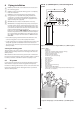
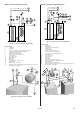
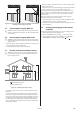
DHP-AL, connection diagram VLD
General connection diagram DHP-AL, system VLD.Figure 49:
Position Name
1 Heat pump (part of the delivery)
2 Supply line
3 Return line
4 Safety valve
5 Expansion tank
6 Strainer (part of the delivery)
7 Flexible hoses (part of the delivery)
8 -
9 Mixer valve
10 Exchange valve
11 Safety valve (9 bar) (included in delivery)
12 Vacuum valve
13 Non-return valve
14 Shut-off valve
15 Cold water
16 Hot water
17 Water heater (part of the delivery)
18 Bleed valve at stainless steel water heater
19 External auxiliary heater
20 Circulation pump
21 Non-return valve
22 Moved supply line sensor (included in heat pump)
23 Auxiliary shunt
24 Safety valve for temperature and pressure (mounted only on cer-
tain models, see chapter 6)
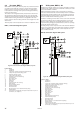
6.4 Safety valves
⚠
Radiator systems with a closed expansion tank must also be
equipped with an approved pressure gauge and safety valve,
minimum DN 20, for a maximum 1.5 bar opening pressure, or
according to country specific requirements.
⚠
Cold and hot water pipes as well as overflow pipes from
safety valves must be made of heat resistant and corrosion-
resistant material, e.g. copper. The safety valve overflow pipes
must have an open connection to the drain and visibly flow
into this in a frost-free environment.
⚠
The connecting pipe between the expansion tank and the
safety valve must slope continuously upwards. A continuous
upwards slope means that the pipe must not slope down-
wards from the horizontal at any point.
6.5 Connecting cold and hot water pipes
1. Connect the cold water and hot water pipes with all the neces-
sary components according to the connection diagram for the
relevant system.
6.6 Connecting the heating system supply
and return lines
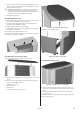
All pipes should be routed in such a way that vibrations cannot be
transmitted from the heat pump through the piping and out into
the building. This also applies to the expansion pipe. To avoid the
transmission of vibrations, we recommend that flexible hoses are
used for the supply line and return line on both the heating system
and brine system sides. Flexible hoses are available to purchase
from Danfoss AS. The figures below show how appropriate and
inappropriate installations look using this type of hose.
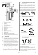
To avoid noise caused by pipe mounting, rubber-coated clamps should
be used to prevent the transmission of vibrations. However, installation
should not be too rigid and the clamps must not be too tight.
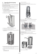
Do not twist the flexible hoses as they are installed. At Figure 50:
threaded connections, use a counterhold spanner.
Cut the hose to the correct length to avoid excess Figure 51:
bowingout or stretching at bends.
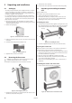
Cut the hose to the correct length to avoid excess bowing- Figure 52:
out or stretching and offset the ends so that the hose is not
installed completely straight.
Use fixed pipe bends to avoid excess stress on bends next to Figure 53:
connections.
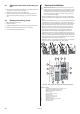
1. Connect the supply line with a flexible hose connection and
with all the necessary components.
2. Connect the return line with a flexible hose connection and
with all the necessary components including a filter.
3. Insulate the supply and return lines.
4. Connect the expansion tank to the expansion outlet (22mm Cu)
on the top of the heat pump.
11
4
5
7
7
12
13
23 10
14
13 14
24
16
15
1
18
17
22
19
20
21
6
2
3