Installation and service instructions DHP-AL VMBME102
Table of contents Installation instructions ................... 5 Service instructions .......................... 23 1 Important information/Safety regulations . . . . . . . . . . . . . . . . . . 5 1.1 Refrigerant. . . . . . . . . . . . . . . . . . . . . . . . . . . . . . . . . . . . . . . . . . . . . . . .5 1.2 Electrical connection . . . . . . . . . . . . . . . . . . . . . . . . . . . . . . . . . . . . . .5 1.3 Commissioning . . . . . . . . . . . . . . . . . . . . . . . . . . . . . . . . . . . . . . . .
Installation instructions 1 Important information/Safety regulations ⚠ The heat pump must be installed by authorised installation engineers and the installation must follow the applicable local rules and regulations as well as these installation instructions.
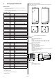
2 Dimensions and connections Heat pump information The brine pipes can be connected on either the left or right-hand sides of the heat pump. Delivery check 1. Check that there is no transport damage. The heat pump is packaged in cardboard. 2. Remove the plastic wrapping and check that the delivery contains the following components. Sizes 6 kW - 10 kW: Part no.
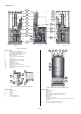
Components 1 1 2 2 3 3 4 4 5 13 6 14 7 15 8 9 10 16 11 12 Left view Front view Right view Figure 3: Components.
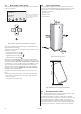
2.1 2.2 Heat pump control panel The heat pump control panel consists of a display, four control buttons and an indicator. 20°C ROOM (20°C) NO DEMAND HEAT OPERAT. AUTO The symbols in the display are only examples. Certain symbols cannot be displayed at the same time.
in a newly-built house, this has normally been taken into account during construction, and the joists where the heat pump will be located have been reinforced. Always check that this has been carried out when installing into a newly-built house. Avoid positioning the heat pump in a corner as the surrounding walls may amplify its noise. It is also important to adjust the heat pump using the adjustable feet so that it is horizontal to the base. 2.
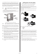
4 4.2 Unpacking and installation ⚠ 4.1 Setting up Both the heat pump and water heater are prepared to be connected together, either to the left or right of each other. When setting up the heat pump and water heater, the heat pump must be placed in the direction of where the brine pipes are to be connected. The water heater should then be placed on the opposite side and should be positioned next to the heat pump.
4 Figure 15: Front cover preparations. 6 7 8 Screw the three screws (4) into place from underneath in the pre-drilled holes at the front edge of the outdoor unit. Hook the lower edge of the front cover onto the three protruding screws. Secure the front cover using three screws in the pre-drilled holes (5). Figure 18: Finishing by installing the cover. 11 Hook the cover onto the stand. NOTE! Remember that the water that drips from the outdoor unit during defrost must be able to drain into the ground.
5 Piping installation ⚠ NOTE! To prevent leaks ensure that there are no stresses in the connecting pipes! ⚠ NOTE! It is important that the heating system is completely bled after installation. ⚠ NOTE! Bleed valves must be installed where necessary. • Ensure that the piping installation follows the dimension and connection diagrams in section “Heat pump information”. • Piping installation must be carried out in accordance with applicable local rules and regulations.
5.2 Safety valves • Radiator systems with a closed expansion tank must also be equipped with an approved pressure gauge and safety valve, minimum DN 20, for a maximum 3 bar opening pressure, or according to country specific requirements. • Cold and hot water pipes as well as overflow pipes from safety valves must be made of heat resistant and corrosion-resistant material, e.g. copper.
6 ⚠ Electrical Installation Electrical current! The terminal blocks are live and can be highly dangerous due to the risk of electric shock. The power supply must be isolated before electrical installation is started. The heat pump is connected internally at the factory, for this reason electrical installation consists mainly of the connection of the power supply. • The electric installation must only be carried out by an authorised electrician.
• If the sensor cable is connected through a pipe, the pipe must be sealed so that the sensor is not affected by outgoing air. Then connect the sensor to the heat pump control system in accordance with the instructions below. 1. Route the outdoor sensor connection cable through the cable bushing in the top panel to the terminal block. 2. Connect the sensor to the terminal blocks according to the connection diagram. 6.4 6.
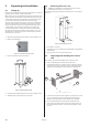
7 Brine installation 7.1 Connection diagram Pipe connections in image: 1 Brine out, during defrosting 3 Brine in 6 Brine out, normal operation 7 Brine in, during defrosting 10 Brine out, during defrosting 14 Brine expansion line when outdoor unit is positioned at high level Safety valve 1.5 bar Moved supply pipe sensor for the brine system 14 Bleed valve 10 13 11 12 9 6 5 Alternative 2 Location of the brine expansion tank when the outdoor unit is higher than the heat pump. 4 Safety valve 1.
7.2 Installing brine pipes 1. Determine which side of the heat pump brine pipes are to be connected. 2. Route the return pipe through the return pipe rubber bellows on the side of the heat pump. 3. Install the return pipe with all the accompanying components. Remember to install the filler cock with the filter cover turned upwards. 4. Route the supply pipe out through the supply pipe rubber bellows on the side of the heat pump. 5. Install the supply pipe with all the accompanying components. 6.
7.4 Bleeding and post filling the brine circuit ⚠ NOTE! When topping up, the brine pump must be running. 1. Start the brine pump in the control computer menu SERVICE -> MANUAL TEST -> BRINEPUMP, set the value to 1. 2. Check that the level in the bleed tank (9) has stabilised. If the level is not stable there is air in the system. 3. Dismantle the safety valve (8) on the bleed tank. 4. Top up with brine to 2/3 of the tank through the connection on which the safety valve (8) was installed. 5.
8.4 ⚠ Higher hot water temperature NOTE! Never connect the heat pump to provide a higher temperature unless the heating or hot water systems require it. Higher temperatures increase the load on the heat pump. If necessary, the heat pump can be connected to produce hotter water for the heating system and hot water system when it is installed. A B Figure 40: The pressure switches are installed on the compressor’s pressure pipe. 1.
9 Start up NOTE! Read the safety instructions! The installation may only be commissioned if the heating ⚠ system, water heater and brine system have been filled and bled. Otherwise the circulation pumps can be damaged. ⚠ 9.1 If the installation is only to be run on auxiliary heating, first ensure that the heating system is filled and bled and that neither the brine pump nor the compressor can be started. This is carried out by setting the operating mode to ADD.HEAT.
⚠ Starting circulation pumps manually NOTE! Risk of burns, the pipe can reach 70-80°C! If any of the circulation pumps do not start, it may need to be helped as follows: Figure 42: Bleed screw location. 1. Open and remove the bleed screw on the front of the pump. Normally a small amount of water comes out when it is removed. 2. Insert a flat blade screwdriver and turn it in the direction of rotation of the pump (clockwise). 3. Reinstall the bleed screw with its rubber seal.
10 Handover to customer After installation and test operation, the customer must be informed about their new heat pump installation.
Service instructions 11 The heat pump 11.1 General function description A heat pump utilises the free solar energy found in a natural heat source, such as rock, ground, ground water or air.. The heat pump can be compared to a reversed refrigerator. In a refrigerator, heat is transferred from the inside of the refrigerator to the outside. In a heat pump the heat that is stored in a heat source is transferred to the inside of the house.
11.2 Components DHP-AL is a heat pump installation for both heating and producing domestic hot water for the home. The heat pump uses outdoor air as a heat source and retrieves energy from the air using an air heat exchanger in a separate outdoor unit. The compressor in the heat pump is first compressor on the market that is specially developed for heat pumps.
11.4 Heating Heating is active when the outdoor temperature is the same as or greater than 17°C (adjustable value for HEAT STOP) and other operating conditions are met, see the “Operating conditions ” section for more information. When the outdoor temperature is greater than 17°C heating stops. Outdoor temperature Heating not permitted at outdoor temperature greater than HEAT STOP. HEAT STOP (17°C) Heating permitted with compressor + addition between HEAT STOP and OUTDOOR STOP.
11.7 Important parameters Heat production - calculating The indoor temperature is adjusted by changing the heat pump’s heat curve, which is the control computer’s tool for calculating what the supply temperature should be for water that is sent out in the heating system. The heat curve calculates the supply temperature depending on the outdoor temperature. The lower the outdoor temperature, the higher the supply temperature.
ROOM If you wish to increase or reduce the indoor temperature, change the ROOM value. The difference between changing the ROOM value and the CURVE value is that the system’s heat curve does not become steeper or flatter if the ROOM value is changed, which the curve becomes if the CURVE value changes, instead the entire heat curve is moved by 3°C for every degree change of the ROOM value.
maintaining the heat in the basement in the summer is that all radiators have thermostat valves that switch off the heat in the rest of the house. It is extremely important that the heating system and the radiator valves are trimmed correctly. As it is usually the end customers themselves who have to carry out trimming, remember to inform them how to carry it out correctly. Also remember that the value for HEATSTOP needs adjusting upwards for summer heating.
HYSTERESIS In order to start the heat pump in advance during sudden changes of the heat demand, there is a value, HYSTERESIS, which controls the difference between the actual supply temperature, t1 and the calculated supply temperature, t2. If the difference is the same or greater than the set HYSTERESIS value (x), i.e.
12 Control computer 12.1 Function description A control computer is used to automatically calculate the heat demand in the house where the heat pump is installed and to ensure that the correct amount of heat is produced and emitted where necessary. There are many different values (parameters) that must be referred to during the calculation of the heat demand. During installation use the control computer to set and change certain values that have to be adapted according to the house demand.
12.2 Display The display of the control computer shows information about the heat pump’s operation, status and any alarms, in text form. The status, indicated by symbols, is also shown in the lower section which shows the heat pump’s active process. Operating mode Appears with applicable heat pump operating status text. Operating mode Meaning The installation is fully switched off.
Message Meaning NO DEMAND HEAT Indicates that there is no heating production demand. HIGHPRESS ERROR Alarm that indicates that the high pressure switch has deployed. LOWPRESS ERROR Alarm that indicates that the low pressure switch has deployed. MOTOR P ERROR Alarm that indicates that the motor protection has deployed. BRINEFLOW LOW Appears if the accessory flow switch is installed. Alarm that indicates that the flow in the brine system is low. SENSOR Alarm that indicates a faulty sensor.
13 Menus 13.1 Main menu INFORMATION This menu is used to change the heat pump’s operating modes and adjust the heat curve. History and operating times can also be viewed here. Open the menu by pressing the left or right button. The sub menus available in the INFORMATION menu are shown in the following table: Main menu Sub menu Selection/settings INFORMATION OPERATION Ø AUTO HEATPUMP ADD.
Sub menu INFORMATION -> OPERATION Used to select operating mode. Menu selection Meaning Factory setting The installation is off. Any active alarms reset. - AUTO Automatic operation with both heat pump and auxiliary heater permitted. If the number of power stages for auxiliary heating are set to zero (SERVICE -> AUX. HEAT -> MAX STAGE) only AUTO or OFF can be selected as operating mode. - HEATPUMP Operation with only heat pump permitted.
Sub menu INFORMATION -> TEMPERATURE Used to indicate the prevailing temperatures, history and set/calculated values. History can be accessed to view all the values by pressing the right arrow to present a graph of the last 100 measurement points for the set time interval (SERVICE -> INSTALLATION -> LOGTIME). In the event of an alarm, history stops being logged until the alarm is reset by changing the operating mode to OFF.
13.2 Main menu SERVICE This menu is for use during installation and service to optimise and adjust the operation of the heat pump. Access the menu by holding the left and right arrows in for 3 seconds. The sub menus available in the SERVICE menu are shown in the following table: Main menu Sub menu Selection/settings SERVICE HOT WATER START HOT WATER TIME HEATING TIME TOPH.INTERVAL TOPH.
Sub menu SERVICE -> HOT WATER Used to change the settings for hot water production. Menu selection Meaning Factory setting START Start temperature for hot water production. Shows the actual hot water temperature and the value within brackets indicates the start temperature. 40°C (at OUTSIDE AIR temperature of 38°C) (interval: 30°C / 55°C) HOT WATER TIME Time for hot water production during combined hot water and heating demand, in minutes.
Sub menu SERVICE -> MANUAL TEST Used to manually test and test operate the heat pump’s components or signal outputs. Menu selection MANUAL TEST Meaning Factory setting Setting options for manual test. - 0 = deactivate manual test 1 = activate manual test 2 = activate manual test with option of navigating from the SERVICE menu to check that the temperatures rise. HEATPUMP 0 = stop heat pump, does not stop started brine pump 1 = start heat pump, also starts brine pump.
Sub menu SERVICE -> INSTALLATION Used for settings that are set during installation Menu selection Meaning Factory setting SWEDISH Language setting for the control computer. SWEDISH (SVENSKA NORSK, SUOMI, DEUTSCH, NEDERLANDS, ENGLISH, FRANCAIS POLSKI DANSK) SYSTEM NOTE! The menu selection in the SYSTEM menu varies depending on the selected values. Tip: start in the top menu and work downwards.
Sub menu SERVICE -> DEFROST Used to change settings for outdoor unit defrost. Menu selection Meaning Factory setting DEFR CURVE 0 Here, the angle of the defrost curve, starting at an outdoor temperature of 0°C, can be changed using the right-hand arrow and by either pressing + or – (changes the start temperature for defrosting).
14 ⚠ Troubleshooting NOTE! This troubleshooting section contains general heat pump information for the whole range and can therefore contain certain points that do not apply to the installed heat pump. 14.1 Alarm list Shown in display in the event of an alarm. To reset alarms 1-5. set the operating mode to OFF or cut the power supply. Message Meaning HIGHPRESS ERROR Tripped high pressure switch. Compressor stopped. No hot water production. LOWPRESS ERROR Tripped low pressure switch.
14.3 Operational problems – Alarm Problem – Alarm LP (low pressure pressure switch) Cause Troubleshooting Remedy 1. Blocked strainer on the brine circuit. Check that the strainer is not blocked. Clean the strainer if necessary. 2. Air in the brine circuit. Listen for air in the heat pump and brine circuit. Bleed the brine circuit according to the installation instructions. 3. Closed taps, main tap or filler cock on the brine circuit. Check that the shut-off cock/any other taps are open.
Cause Troubleshooting Remedy 13. Drying filter blockage. Check the temperature difference above the drying filer. A one degree difference is permissible. If the difference is greater than 1 degree, the filter is blocked. Take a reading during operation. If the drying filter is sealed, replace it. 14. Blocked evaporator on the water side.
Cause Troubleshooting Remedy 7. The operating pressure switch does not open. • Incorrect pressure switch installed. Same or higher break pressure than high pressure pressure switch. See marking. If the operating pressure switch does not open, replace it. • Pressure switch fault, opens at a higher pressure than indicated (mark pressure). Check using the manometer apparatus. • Defective pressure switch, never opens. 8. The high pressure pressure switch opens too soon.
Problem – Alarm MS (motor protection) Cause Troubleshooting Remedy 1. Phase drop or blown fuse. Check that all phases are present on the terminal block for incoming supply. If not, check the fuses in the cabinet. If any of the phases are not present, check backwards towards the building’s main electrical cabinet. If there are no phases there, contact the network supplier.
Problem – Incorrect phase sequence Cause Troubleshooting Remedy The incoming phases have the incorrect sequence (only applies to 3-phase heat pumps). • If the text ERR PHASE SEQ appears in the display when the heat pump is powered, (only appears in the first 10 minutes) this means that the phases have the incorrect sequence. If the phases are in the incorrect order, switch two incoming phases at the main terminal block and recheck according to the troubleshooting window.
Problem – Alarm Brine flow low Cause Troubleshooting Remedy 1. Incorrect system selected in the control computer. In the menu SYSTEM, check which is selected. If the incorrect system is selected , change it. • Check whether the ground water pump is running? The ground water pump must start and run together with the heat pump’s integrated brine pump. If the system does not contain a flow switch but the control computer is set for the system with flow switch, this alarm occurs. 2. Insufficient flow.
Cause Troubleshooting Remedy 5. Lack of refrigerant, not enough refrigerant in the system. Using manometer apparatus and thermometer, check that the unit’s overheating is correct for the specific refrigerant. If cooling is not at the correct level compared with the specific refrigerant and is too low, there is insufficient refrigerant in the unit. Follow the correct procedure (depending on type of refrigerant) to add the correct amount of refrigerant.
Cause Troubleshooting Remedy 14. Anti-freeze is forced out of the safety valve on the expansion tank (brine system). During the winter, water surrounding the hoses in the borehole can freeze. In some cases, the ice can push against the hoses slightly. Due to the reduction in volume in the hose, the anti-freeze fills the expansion tank and eventually forces some fluid out of the safety valve.
Problem – Shrieking whistling noise Cause Troubleshooting Remedy 1. Whistling expansion valve. 1. Take overheating readings, adjust to the recommended value. Check if the noise has stopped, if not, continue with point 2. 2. Open and close the valve fully in and out. Continue with point 3. 3. Adjust the expansion valve to recommended overheating value again. If the problem persists, replace the expansion valve. 2. Noise from the soft-starter.
Cause Troubleshooting 4. Start temperature set too high for hot water production. Check that the start temperature is correctly • If the start value is set too high, reduce it set. Should not be set above the factory set to the factory set value. value. • If the system has a high (>+8°C) brine temperature, you may have to reduce the start value further for a longer running time. 5. Sensor fault, hot water sensor.
14.7 Operational problem – Heating comfort Problem – Too cold Cause Troubleshooting Remedy Check the ROOM and CURVE and MAX set1. The heat pump’s control computer is not set/adjusted to the customer’s requirements/ tings. wishes. Adjust incorrect values in the heat pump’s control computer. ROOM = Desired indoor temperature CURVE = Should be set so that the desired indoor temperature (ROOM) is maintained regardless of the outdoor temperature.
Cause Troubleshooting Remedy 9. The external auxiliary heater does not start when the heat pump’s control computer requests it. If an external auxiliary heater is used, check that it is correctly installed by test running it in MANUAL TEST – ADD.HEAT - 1. Connect the external auxiliary heater according to the instructions. If it does not start at manual test operation, check that the start signal/voltage comes from the heat pump. See wiring diagram.
Problem – irregular indoor temperature Cause Troubleshooting Remedy 1. The heat pump’s control computer is not set/adjusted to the customer’s requirements/wishes. Check the ROOM and CURVE, MIN, MAX CURVE5, CURVE0, CURVE-5 and HEATSTOP settings. Adjust incorrect values in the heat pump’s control computer. ROOM = Desired indoor temperature CURVE = Should be set so that the desired indoor temperature (ROOM) is maintained regardless of the outdoor temperature.
Problem – Runs on electric heating element Cause Troubleshooting Remedy 1. Operating mode ADD.HEAT is selected. If this operating mode is selected, the auxiliary heater is used for heating and hot water production, not the compressor. If ADD.HEAT mode is selected and you no longer want it, change to AUTO, the heat pump then controls both the compressor and auxiliary heater. 2. The compressor cannot run due to an alarm. Check the alarm that is indicated in the display.
Cause Troubleshooting Remedy 3. The compressor cannot run due to an alarm. Check the alarm that is indicated in the display. Rectify the problem and rest the alarm. See the “Operational problem – Alarm” section. 4. The heat pump has stopped on high return. • Check what the MAX value is set at in the heat pump’s control computer.
Cause Troubleshooting Remedy 5. The heat pump’s control Check the ROOM and CURVE and MIN settings. computer is not set/adjusted to the customer’s requirements/ wishes. Adjust incorrect values in the heat pump’s control computer. ROOM = Desired indoor temperature. CURVE = Should be set so that the desired indoor temperature (ROOM) is maintained regardless of the outdoor temperature. MIN = Lowest set-point value on the supply pipe regardless of the outdoor temperature. 6.
Cause Troubleshooting Remedy 11. Lack of refrigerant, not enough refrigerant in the system. Using manometer apparatus and thermometer, check that the unit’s overheating is correct for the specific refrigerant. 12. Overfilled refrigerant circuit. Using manometer apparatus and thermometer, check that the unit’s overheating is correct for the specific refrigerant. 13. Short active collector, e.g. short or dry bore hole, short surface soil collector.
Cause Troubleshooting Remedy 5. Changed conditions. Have you increased your heating and/or hot water demand? • If the heat pump has been dimensioned for a certain demand and this demand is increased, the heat pump might not be able to maintain the desired room temperature. If the heat pump cannot cope with the demand, replace it with one with a higher output or supplement it with a higher output auxiliary heater.
14.9 Operational problem – Outdoor unit Problem – Noise/loud noise Cause Troubleshooting Remedy 1. Positioning the outdoor unit. Determine whether the outdoor unit can be When positioning the outdoor unit, its moved to a more suitable location. direction does not affect its performance. The outdoor unit does not need to be positioned as close to the heat pump as necessary, it can be positioned as far as 30 ”pipe metres” way. 2. Connection/wall lead-ins.
15 Technical data DHP-AL Refrigerant type Refrigerant, kg Electrical connection, V Rated max output, comp. kW Compressor+AH2) 3) 4) Electric heating element, kW Fuse, A Fuse, A cont. Specified output, kW1) Efficiency incl. circ.pump and fan1), COP Specified output, kW2) Efficiency incl. circ.
VMBME102