
Installation guide


12
VMBME102
5 Piping installation
⚠
NOTE! To prevent leaks ensure that there are no stresses in
the connecting pipes!
⚠
NOTE! It is important that the heating system is completely
bled after installation.
⚠
NOTE! Bleed valves must be installed where necessary.
• Ensure that the piping installation follows the dimension and
connection diagrams in section “Heat pump information”.
• Piping installation must be carried out in accordance with appli-
cable local rules and regulations. The hot water tank must be
equipped with an approved safety valve (supplied).
11
4
5
7
7
12
13 14
16
15
1 17
18
6
2
10
9
3
8
1
2
3
4
5
6
7
8
9
10
11
12
13
14
Mixer valve
Strainer
Bleed valve at stainless
steel water heater
Bleed valve
Safety valve 9 bar
Filler cock
Safety valve (not included)
Heat pump
Water heater
Pipe connections in image:
2 Water heater, return pipe
4 Heating system supply pipe
5 Heating system return pipe
8 Heating system, return pipe
9 Bleed valve, at stainless steel water heater
11 Tap hot water
12 Cold water
13 Water heater, supply pipe to TWS coil
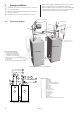
Figure 19: Principle solution for a pipe installation.
Figure 20: General connection diagram.
Position Name
1 Heat pump
2 Supply pipe
3 Return pipe
4 Safety valve (not included)
5 Expansion tank (not included)
6 Strainer
7 Flexible hoses
8 Bleed valve
9 Mixer valve
10 Exchange valve
11 Safety valve (9 bar)
12 Vacuum valve
13 Non-return valve
14 Shut-off valve
15 Cold water
16 Hot water
17 Water heater
18 Bleed valve at stainless steel water heater
5.1 Connection diagram