
Installation guide


14
VMBME102
6 Electrical Installation
⚠
Electrical current! The terminal blocks are live and can be
highly dangerous due to the risk of electric shock. The power
supply must be isolated before electrical installation is start-
ed. The heat pump is connected internally at the factory, for
this reason electrical installation consists mainly of the con-
nection of the power supply.
• The electric installation must only be carried out by an author-
ised electrician.
• The electric installation must follow applicable local and national
regulations.
• The electrical installation must be carried out using permanently
routed cables. It must be possible to isolate the power supply
using an all-pole circuit breaker with a minimum contact gap of 3
mm. (The maximum load for externally connected units is 2A).
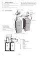
• Electrical connection can also cause noise so this installation
must be carried out appropriately. The figure below shows an
appropriate installation. There is approximately 300mm free
cable between the heat pump and building, however, this
requires the cable to be securely installed onto the top panel so
that the cable cannot be fed into the heat pump. It is inappropri-
ate to bolt trunking between the heat pump and the wall. This is
because vibrations can then be transmitted from the heat pump
through the trunking to the walls of the house.
Figure 25: Recommended distance between trunking on the wall and
trunking on the heat pump is 300mm.
Figure 26: The location of the components on the electrical panel.
Position Name
1 Terminal block
2 Terminal block (applies to the expansion card)
3 Space for expansion card
4 Terminal block
5 Space for Thermia/Danfoss Online
6 Warning decal
7 Defroster card
8 Contactor for compressor
9 Automatic fuses
10 Resetting overheating protection
11 Control computer
12 Soft starter card (Only available for 400 V)
6.1 Connecting the power supply, three
phase 400V AC
⚠
NOTE! The power cable may only be connected to the termi-
nal block intended for this purpose. No other terminal blocks
may be used!
Figure 27: Incoming cable to heat pump with circuit breaker.
⚠
NOTE! Supplied with the jumpers shown in the figure.
1. Route the power cable through the opening in the top panel of
the heat pump to the terminal blocks.
2. Connect the power cable to the terminal block.
6.2 Connecting the power supply, single
phase 230V AC
⚠
NOTE! The power cable may only be connected to the termi-
nal block intended for this purpose. No other terminal blocks
may be used!
Figure 28: Incoming cable to heat pump.
1. Route the power cable through the opening in the top panel of
the heat pump to the terminal blocks.
2. Connect the power cable to the terminal block.
6.3 Connecting the outdoor sensor
⚠
NOTE! The outdoor sensor is connected with extra low pro-
tection voltage. Follow the specific installation instructions
for the outdoor sensor!
Figure 29: Connecting the outdoor sensor.
• Position the outdoor sensor on the north or north west side of
the house.
• To measure the outdoor temperature as accurately as possible,
the sensor must be positioned 2/3 of the way up the facade on
houses up to three storeys high. For higher buildings, the sensor
should be positioned between the second and third storeys. Its
location must not be completely protected from the wind but
not in a direct draft. The outdoor sensor should not be placed on
reflective panel walls.
• The sensor must be positioned at least 1 m from openings in the
walls that emit hot air.
RUM 20C
INGET BEHOV VÄRME
DRIFT AUTO
RUM 20C
INGET BEHOV VÄRME
DRIFT AUTO
1 2 3
5
7
6
4
8
9
121110
N3
3L1
PE5
1L1
1L2
1L3
2L1
2L2
2L3
PE1
Incoming 400V heat pump
Bridged on
delivery
Incoming 230V heat pump
Incoming 230V external auxiliary heater
1L1
N2
PE1
2L1,2L1
2L1,2L2
N3
PE4
305
306