
Installation guide


15
VMBME102
• If the sensor cable is connected through a pipe, the pipe must be
sealed so that the sensor is not affected by outgoing air.
Then connect the sensor to the heat pump control system in
accordance with the instructions below.
1. Route the outdoor sensor connection cable through the cable
bushing in the top panel to the terminal block.
2. Connect the sensor to the terminal blocks according to the con-
nection diagram.
6.4 Changing the language in the control
computer
If necessary, change the language in the control computer menus.
1. Ensure that the main circuit breaker is on.
2. Open the SERVICE menu by pressing
and for three seconds.
3. Change language in the control computer menu SERVICE ->
INSTALLATION -> ENGLISH, select language
and .
6.5 Changing the number of auxiliary heat-
ing power stages
⚠
NOTE! Setting the maximum permitted number of power
stages for the auxiliary heating must be carried out.
1. Ensure that the main circuit breaker is on.
2. Open the SERVICE menu by pressing
and for three sec-
onds.
3. Change the number of auxiliary heating power stages in the
control computer menu SERVICE -> ADD.HEAT -> MAXSTEP,
select the number of stages
and .
6.6 Connecting the outdoor unit
⚠
NOTE! The power cable may only be connected to the termi-
nal block intended for this purpose. No other terminal blocks
may be used!
For correct connection between the heat pump and the outdoor
unit, 6 connections must be made. For more information about
connection, see separate sheet with electrical instructions.
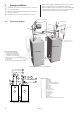
Figure 30: Connecting the outdoor unit.
1. Route the power cable through the opening in the top panel of
the heat pump to the terminal blocks.
2. Connect the power cable to the terminal block.
6.7 Connecting the defroster sensor
Figure 31: Connecting the defroster sensor.
Position the defroster sensor on the reverse of the outdoor unit.
1. Route the defroster sensor connection cable through the cable
bushing in the top panel to the terminal block.
2. Connect the sensor to the terminal blocks according to the con-
nection diagram.
6.8 Connecting the exchange valve
Figure 32: Connecting the exchange valve.
1. Route the exchange valve’s connection cable through the cable
bushing in the top panel to the terminal block.
2. Connect the exchange valve to the terminal blocks according
to the connection diagram.
PE
220
211
213
283
104
218
386
387
N/220
211
213
111
104
218
0V
fan high speed
fan low speed
fan motor protection
cut out
386
387
2
6
3
N
214
217C