
Installation guide


16
VMBME102
7 Brine installation
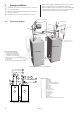
7.1 Connection diagram
Position Name
1 Return pipe, brine
2 Supply pipe, brine
3 Shut-off valve (part of the filler cock)
4 Shut-off valve (part of the filler cock)
5 Shut-off valve (part of the filler cock)
6 Strainer (part of the filler cock)
7 Shut-off valve (part of the filler cock)
8 Safety valve (1.5 bar)
9 Bleed and expansion tank
10 Shut-off valve
11 Pressure tank
12 Outdoor unit
13 Flexible hoses
(not included)
14 Bleed valve (not included)
Alternative 2
Location of the brine
expansion tank when the
outdoor unit is higher
than the heat pump.
1
2
3
4
5
6
7
8
9
10
11
12
13
14
Alternative 1
Location of the brine circuit’s bleed
and expansion tank when the out-
door unit is located at the same level
or lower than the heat pump.
Bleed valve
Moved supply pipe sensor for the
brine system
Safety valve 1.5 bar
Shut-off valve
Filler cock
Brine flow during
defrosting
Safety valve 1.5 bar
Heat pump
Water heater
Brine circuit
Pipe connections in image:
1 Brine out, during defrosting
3 Brine in
6 Brine out, normal operation
7 Brine in, during defrosting
10 Brine out, during defrosting
14 Brine expansion line when outdoor
unit is positioned at high level
Figure 33: Principle solution for pipe installation.
Heat pump Water heater
If the outdoor unit is installed
higher than the heat pump
the expansion outlet must be
used together with a pres-
sure tank.
If the outdoor unit is installed at the same
level or lower than the heat pump, the
accompanying plastic vessel can be used.
The upper part of the outdoor unit must
then not exceed the fluid level in the
vessel.
Figure 34: Connection diagram for brine pipes.