
Installation guide


52
VMBME102
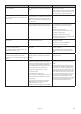
14.7 Operational problem – Heating comfort
Problem – Too cold
Cause Troubleshooting Remedy
1. The heat pump’s control computer is not
set/adjusted to the customer’s requirements/
wishes.
Check the ROOM and CURVE and MAX set-
tings.
Adjust incorrect values in the heat pump’s
control computer.
ROOM = Desired indoor temperature
CURVE = Should be set so that the desired
indoor temperature (ROOM) is maintained
regardless of the outdoor temperature.
MAX = Highest set-point value on the supply
pipe regardless of the outdoor temperature.
2. Incorrect operating mode set in the heat
pump’s control computer.
Check which operating mode is set. If the incorrect operating mode is set,
change to the desired operating mode.
3. Sensor fault, OUTDOOR/ROOM/SUPPLY
PIPE/RETURN PIPE.
Check what the relevant sensor shows, is it a
plausible/actual value?
Measure the resistance of the sensor, check
against the ohm table in the “Measurement
points” section.
If the sensor is defective, replace it.
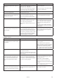
4. The 3-way valve has jammed in hot water
mode.
1. Check the function of the 3-way valve
motor by test running it manually. If the
motor does not shift mode during manual
test operation, check that there is voltage to
the motor, see wiring diagram.
2. Detach the motor and test closing and
opening of the valve by pressing the control
arm.
1. Is the motor being supplied with voltage
according to the wiring diagram in both
operating instances?
MANUAL TEST – VXV HOT WATER
0=Radiator mode, arm out from valve.
1=Hot water mode, arm positioned towards
the valve.
If there is voltage to the motor but the arm
does not shift mode, replace it.
2. Take out and clean the jammed insert, or
replace with a new insert.
5. Defective electric heating element. Use a buzzer and check if all coils in the elec-
tric heating element are intact.
If the electric heating element is defective,
replace it.
6. The heat pump has stopped on HIGH
RETURN.
• Check what the MAX RETURN value is set at
in the heat pump’s control computer. It must
be adjusted to the unit’s maximum supply
temperature and the system’s delta tem-
perature so that it does not cut at too high a
return temperature when the highest supply
temperature is transmitted.
• Check what the return pipe sensor shows,
is it a plausible/actual value? If not, take
a resistance reading from the sensors
and check against the ohm table in the
“Measurement points” section.
If the MAX RETURN value is not adjusted for
the system according to the troubleshooting
window, adjust it.
If the sensor is defective, replace it.
7. Heat production is stopped by the
HYSTERESIS function.
If the flow temperature rises as soon as heat
production is stopped by HYSTERESIS before
INTEGRAL reaches 0, there may be heating
deficit in the house.
• Check if heat production stops because
the hysteresis value is set too low? (See the
installation instructions for factory setting.)
• Check if heat production stops because
thermostats/valves in the heating system are
closed or partially closed?
• Check if heat production stops because the
heating system is under dimensioned?
• Try increasing the hysteresis value until the
heat pump stops on INTEGRAL instead.
• Open thermostats/valves in the heating
system and check that the heat pump stops
on INTEGRAL.
• If the heating system is deemed to be
under dimensioned, the system must be
extended (increase the heat emitting sur-
face).
8. The auxiliary heater is not permitted to cut
in with sufficient output.
Value set too low on MAXSTEP.
MAXSTEP 1 = 3 kW
MAXSTEP 2 = 6 kW
MAXSTEP 3 = 9 kW
MAXSTEP 4 = 12 kW
MAXSTEP 5 = 15 kW
Check the set value on MAXSTEP in the heat
pump’s control computer.
If necessary, adjust the MAXSTEP value in the
heat pump’s control computer.
MAXSTEP 1 = 3 kW
MAXSTEP 2 = 6 kW
MAXSTEP 3 = 9 kW
MAXSTEP 4 = 12 kW
MAXSTEP 5 = 15 kW