
Installation guide


6
VMBME102
2 Heat pump information
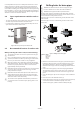
Delivery check
1. Check that there is no transport damage. The heat pump is
packaged in cardboard.
2. Remove the plastic wrapping and check that the delivery con-
tains the following components.
Sizes 6 kW - 10 kW:
Part no. Quantity Name
9680-5796A00 1 Document set
9674-57902001 1 Transparent binder
9360-47054001 1 Safety valve 9 bar 1/2”
9588-51618001 1 Kimsafe outdoor sensor 200 035
9360-56335001 1 Safety valve 1.5 bar 1/2”
9674-24735001 1 Expansion and bleed tank without
valve
9551-54479001 1 Cardboard packaged top for HP
9360-51759007 1 Compression angle joint 28x28
joint
9674-54168001 1 Pipe insulation IT 9x28
3311-55300001 1 Brine in Cu pipe in TWS packaging
9684-48342001 2 Rubber bellows for 22-32mm hole
9674-54164001 1 Pipe insulation F-54-A D=54x9mm
5211-57915001 2 Flexible hose R20 L=600
9360-55453A00 1 Filler cock DN 25
9360-52488001 1 Dirt filter with shut-off DN25
9360-51738005 2 Straight connection LK 303 28xR25
9360-51738008 4 Straight compression connection
22 xR20
Sizes 12 kW :
Part no. Quantity Name
9680-5796A00 1 Document set
9674-57902001 1 Transparent binder
9360-47054001 1 Safety valve 9 bar 1/2”
9588-51618001 1 Kimsafe outdoor sensor 200 035
9360-56335001 1 Safety valve 1.5 bar 1/2”
9674-24735001 1 Expansion and bleed tank without
valve
9551-54479001 1 Cardboard packaged top for HP
9360-51759007 1 Compression angle joint 28x28
joint
9674-54168001 1 Pipe insulation IT 9x28
3311-55300001 1 Brine in Cu pipe in TWS packaging
9684-48342001 2 Rubber bellows for 22-32mm hole
9674-54164001 1 Pipe insulation F-54-A D=54x9mm
5211-50730A00 2 Flexible hose R25 L=600
9360-56911A00 1 Filler cock DN 32
9360-52488001 1 Dirt filter with shut-off DN25
9360-51738005 4 Straight connection LK 303 28xR25
9360-51738008 2 Straight compression connection
22 xR20
The outdoor unit is supplied as a package containing:
• Outdoor unit
• Disassembled stand
• Necessary screws, nuts and washers.
• Defroster sensor
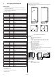
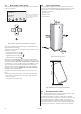
Dimensions and connections
The brine pipes can be connected on either the left or right-hand
sides of the heat pump.
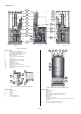
Figure 1: Dimensions and connections.
Position Name
Heat pump
1 Brine out, during defrosting, 28 Cu
2 Return pipe water heater, 28 Cu
3 Brine in
4 Heating system supply pipe, 22 Cu: 6-10 kW, 28 Cu: 12 kW
5 Heating system return pipe, 22 Cu: 6-10 kW, 28 Cu: 12 kW
6 Brine out, normal operation
Water heater
7 Brine in, during defrosting
8 Water heater, return pipe
9 Bleed valve, at stainless steel water heater
10 Brine out, during defrosting
11 Domestic hot water, 22 Cu
12 Cold water
13 Water heater supply pipe to TWS coil
14 Brine, expansion line when outdoor unit is positioned at high level
15 Lead-in power and sensor lead
16 Lead-in sensor lead
17 Lifting point
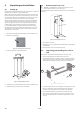
Figure 2: Outdoor unit, Dimensions and connections.
Position Name
1 Brine in (HP Brine out) 28 Cu
2 Brine out (HP Brine in) 28 Cu
1175
630
405
1200
1
12
2
1
4
5
6
10
14
13
9
11
12
17
15
16
2
78
3
Heat pump Water heater