
Installation guide


7
VMBME102
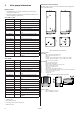
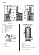
Figure 3: Components.
Position Name
1 Heating system supply pipe
2 Brine, supply during normal operation
3 Return pipe, heating system
4 Auxiliary heating, immersion heater
5 Electrical panel
6 Heating system circulation pump
7 Evaporator
8 Circulation pump coolant system
9 Exchange valve, heating system
10 Drying filter
11 Expansion valve
12 Shunt valve defrosting
13 Brine, supply during defrosting
14 Condenser
15 High pressure and operating pressure switch
16 Compressor
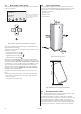
Figure 4: Outdoor unit components and connections.
Position Name
1 Outdoor unit
2 Cover
3 Front cover
4 Stand
5 Cover
6 Connection, brine in
7 Connection, brine out
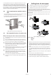
Figure 5: Water heater components and connections.
Position Name
1 Defrosting tank
2 Water heater
3 TWS coil
4 Connection, brine, supply during defrosting
5 Bleed valve, at stainless steel water heater
6 Tap hot water
7 Cold water
8 Connection, to TWS coil
9 Connection, expansion line when outdoor unit is positioned at
high level
10 Connection, brine from heat pump
11 Connection, return pipe to heat pump
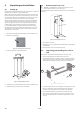
Left view Front view Right view
Components
6
7
1
2
3
4
5
6
4
1
3
9
12
16
14
13
5
8
10
11
15
7
2
4
1
3
2
1
2
3
4 5 6 7
10
11
8 9