
Installation guide


8
VMBME102
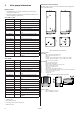
2.1 Heat pump control panel
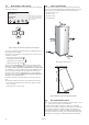
The heat pump control panel consists of a display, four control but-
tons and an indicator.
Figure 6: Display, control buttons and indicator for the heat pump.
The control computer is controlled using a user-friendly menu sys-
tem, displayed in the display.
Use the four control buttons to navigate the menus and increase or
reduce the set values:
• An up button with a plus sign
• A down button with a minus sign
• A right button with a right arrow
• A left button with a left arrow
The main menu, INFORMATION, is opened by pressing the left or
right buttons. From INFORMATION one of the four sub-menus can
be opened: OPERAT.; HEATCURVE; TEMPERATURE and OPERAT. TIME.
For installation or service, a hidden service menu, SERVICE, is used.
This is opened by holding the left and right buttons depressed
for three seconds. From the SERVICE menu one of the following
sub-menus can be opened: WARMWATER; HEATPUMP; ADD.HEAT;
MANUAL TEST and INSTALLATION.
For further information about the menus see the service instruc-
tions.
The indicator at the bottom of the control panel has two modes:
• Lit steadily, the installation has power and is ready to produce
heat or hot water
• Flashing, means an active alarm
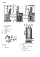
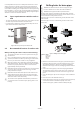
2.2 Space requirement
To facilitate the installation and subsequent testing and mainte-
nance it is recommended that there is sufficient free space around
the heat pump in accordance with the following dimensions:
– 300 mm on each side
– 300 mm above
– 600 mm in front
– 10 mm behind
Figure 7: Necessary service space.
Figure 8: Minimum headroom for heat pump installation.
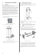
2.3 Recommended location
⚠
To avoid condensation problems for the brine pipes, as short
a brine pipe as possible is recommended.
The heat pump should be located on a stable floor, preferably
made of concrete. When locating the heat pump on a wooden floor
this should be reinforced to take the weight. One solution is to
place a thick metal plate, at least 6mm, under the heat pump. The
metal plate should cover several joists spreading the weight of the
heat pump over a larger area. If the heat pump is being installed
The symbols in the display are
only examples. Certain sym-
bols cannot be displayed at
the same time.
1620
ROOM
20°C
(20°C)
NO DEMAND HEAT
OPERAT. AUTO