ECL Comfort 100M User’s Guide and Installation 2004.05 *087R9728* *vi7ab402* ECL Comfort 100M User’s Guide and Installation 2004.
Table of contents User’s Guide Before you start Operating the controller Setting the clock Individual comfort and reduced comfort periods Controller mode Temperature setting Temperature reduction Setting the heat curve Controller settings on the rear side Page No.
User’s Guide Before you start Save energy - save money - improve your comfort temperature The ECL Comfort controller is designed by Danfoss for the automatic temperature control of heating systems. The advantages of the ECL Comfort controller system are the security of your heating control and the optimum use of energy resources. Seasonal changes and variations in outdoor temperatures are monitored by the control system.
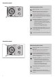
Operating the controller Setting the clock Clock (optional) A clock can be mounted when an automatic change between comfort temperature and reduced temperature is desired. 1 6 2 18 12 6 12 18 18 6 12 3 9 12 6 Turn the minute hand to set the actual week day (7-day clock) and time. 12 18 18 6 Setting the clock Note! You will move the entire outer ring of the clock with its sliders, just by turning the minute hand.
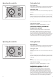
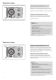
Controller mode What do the symbols mean? 1 6 2 18 12 6 12 18 18 6 12 3 9 12 6 12 18 18 6 Manual operation. Used only at maintenance and service. Note! The system protection against frost is switched off when this mode is selected. 6 18 12 6 Constant comfort temperature. The day plan is not in operation. Used when ex tended periods of comfort temperature are desired, i.e. a day off work or a late-night party. Automatic operation. This is the normal mode.
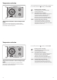
Temperature setting Temperature setting without room sensor (parallel displacement of the heat curve) 1 6 2 18 12 6 12 18 18 6 12 3 9 12 6 If you have no room sensor installed, your system will not know the exact room temperature. Therefore you can only use the temperature setting button to change the flow temperature. This corresponds approx. to a possible change in room temperature of +/- 8 °C.
Temperature reduction The knob (potentiometer) for the temperature reduction can be set in the positions of (standby), 1 - 14 or AUTO: 1 6 2 18 Heating system on standby The heating system is stopped, but still protected against frost. 12 6 12 18 18 6 12 3 9 12 6 12 18 18 6 1 - 14 Fixed temperature reduction Without room sensor: The flow temperature is decreased in order to obtain the desired reduction of the room temperature.
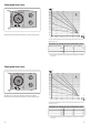
Setting the heat curve ˚C 1.8 90 1 6 2 18 12 1.2 80 6 12 2.2 18 18 6 12 3 9 12 6 70 12 18 18 6 60 0.6 6 18 12 6 50 40 0.2 30 The heat curve shows the relation between the outdoor temperature and the flow temperature of the heating circuit. 20 ˚C 10 -30 -20 -10 0 10 20 You can set the heating curve slope in the range from 0.2 to 2.2. The slope is factory set to 1.2.
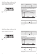
Controller settings on the rear side To make the controller ready for operation, you must adjust the controller settings on the rear side. Switch 1: Heating cut-out Switch 1 Cut-out temperature Mini switches 1 to 8: OFF No cut-out ON 18 ºC Your setting The heating cut-out function helps you save energy. Set the limit for the outdoor temperature at which you want your heating system to stop.
Switch 3: Maximum flow temperature limit Switch 5: Gear motor/thermo actuator Switch 3 Switch 5 Max. flow temperature Your setting Actuator type OFF 45 ºC OFF Thermo actuator ON 90 ºC ON Gear motor Set a maximum flow temperature to protect your heating system from getting overheated. Switch 4: Running time of the motorized valve Switch 4 Running time OFF 20 sec. ON 120 sec. Your setting Select the gear motor or thermo actuator, depending on what is used in your heating system.
Installation and maintenance Before you start Save energy - save money - improve your comfort temperature The ECL Comfort controller is designed by Danfoss for temperature control of heating systems. The ECL Comfort ensures you of the following; • Room temperatures will be adjusted to your personal settings. • Lower temperatures and lower energy consumption reduce costs and ensure optimum use of energy resources. • The automatic pump motion program protects the circulation pump against blocking.
Identifying the system type The ECL Comfort controller is capable of controlling different heating systems. These standard system types cover a variety of system compositions. Heating system type 1: Direct district heating If your system is not quite as the diagrams of the most frequently used systems, find the diagram with the best resemblance with your system and make your own combinations.
Mounting the controller You should mount the ECL Comfort controller for easy access near the heating unit. You can choose between three methods: • Mounting in a panel • Mounting on a wall • Mounting on a DIN rail Screws and rawlplugs are not supplied with this package. Mounting on a wall Order mounting kit No. 087B1154. Mount the terminal box on a wall with a smooth surface. Establish the electrical connections and position the controller in the box. Secure the controller by the fixing screw.
Placing the temperature sensor types It is important that the sensors are mounted in the correct position in your heating system. Room temperature sensor (ESM-10, ECA 60 and 61 remote controls) Outdoor temperature sensor (ESMT type) Place the room sensor in the room where the temperature is to be controlled. Do not place it on outside walls or close to radiators, windows or doors.
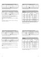
Electrical connections 230 V a.c. Terminal Description Max. load Electrical connections 24 V a.c. Terminal Description Max. load 1 L Voltage supply 230 V a.c. 1 L Voltage supply 24 V a.c. 2 N Voltage supply 230 V a.c. 2 N Voltage supply 24 V a.c. 3 M1 Gear motor - open 0.2 VA 230 V a.c. 3 M1 Gear motor - open 1A 24 V a.c. 4 M1 Gear motor - close alt.: ABV thermo actuator 230 V a.c. supply for M1 Circulation pump for heating circuit 230 V a.c. supply for P1 0.2 VA 230 V a.c.
Electrical connections - sensors LED indication Function test The LED indicator shows whether the 100M is in operation or not. When testing sensors and controller, the control status and faults are shown. Control status Terminal Description 15 and 16 ECL Comfort BUS Type 17 and 16 Outdoor sensor (S1) ESMT 18 and 16 Room sensor (S2) 19 and 16 Flow sensor (S3) ESM-10 ESMU/ESM-11/ESMC At normal operation with the function switch in the positions , the indicator lights.
✐ Check list Is the ECL Comfort controller ready for use? Make sure that the power supply is wired correctly to the terminals 1 (Live) and 2 (Neutral). See page 26. Check the settings on the controller’s rear side. See page 14: Controller settings on the rear side. Check that pumps and valves are connected to the correct terminals. See page 26: Electrical connections Check that all sensors are connected to the correct terminals.
Communication The ECL Comfort controller can be connected to external units via the ECL Comfort BUS. Master / slave systems If the controller is part of a larger system with several controllers, you can connect the controllers with each other and send information to them using the same outdoor sensor. The controller which is physically connected with the outdoor sensor is the master of the entire system and gets the address 15.
Power back-up 1 6 18 2 12 6 12 18 18 6 12 3 9 12 6 12 18 18 6 6 18 12 6 Power back-up for your ECL Comfort controller To ensure power back-up there is a battery placed above the clock. Normally this battery is not in operation. However Danfoss recommends to replace it every 2 years. Use an Alcaline AAA 1.5 V type. Remove the battery holder and replace the battery. Remount the holder again.
Definitions Actual flow temperature The temperature that is measured in the flow at any time. Comfort period A period of the day where comfort temperature is selected. Comfort temperature The temperature maintained in the heating or hot water circuits during comfort periods, which normally means during daytime. Function selector A facility which makes it possible to override the mode of the controller. Heating circuit The circuit for heating the room/building.
38 39 38 39