VI.KT.O1.02 2008.07 C17 Domestic hot-water (DHW) controller www.danfoss.com ECL Comfort Installer's Guide www.danfoss.com VI.KT.O1.02 2008.
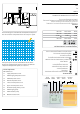
Return temperature sensor S5 Lower tank temperature sensor S6 Upper tank temperature sensor P1 Circulation pump, primary circuit P2 DHW charging pump P3 DHW circulation pump M1 Motorized control valve Adjust- Controller ment mode S4 Circuit Shift selector button DHW temperature sensor Circuit indicator S3 Controller mode Manual operation (used only at maintenance and service) Scheduled operation DHW charging temperature sensor Constant comfort temperature S2 Constant saving temperature
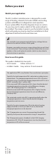
Table of Contents Sections in the Installer’s Guide The documentation for the ECL Comfort controller is composed of numbered sections. Only sections relevant to your ECL Comfort controller are included here. Before you start Installation 10 11 12 14 15 Identifying the system type Mounting the ECL Comfort controller Electrical connections 230 V a.c.
Disposal instruction: This product should be dismantled and its components sorted, if possible, in various groups before recycling or disposal. Always follow the local disposal regulations.
Before you start Sketch your application The ECL Comfort controller series is designed for a wide range of heating, domestic hot-water (DHW) and cooling systems with different configurations and capacities. If your system differs from the diagrams shown in section 10, you may want to make a sketch of the system about to be installed. This makes it easier to use the Installer’s Guide, which will guide you step-by-step from installation to final adjustments before the end-user takes over.
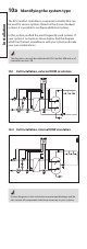
Installation 10a Identifying the system type The ECL Comfort controller is a universal controller that can be used for various systems. Based on the shown standard systems, it is possible to configure additional systems. In this section you find the most frequently used systems. If your system is not quite as shown below, find the diagram which has the best resemblance with your system and make your own combinations. The functions can only be realized with ECL Comfort 300 and as of controller version 1.
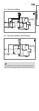
10b 10.3 Minimum installation Installation 10.4 Minimum installation, district heating System diagrams in this instruction are principal drawings and do not contain all components which are necessary in your systems.
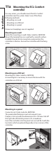
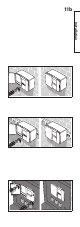
Installation 11a Mounting the ECL Comfort controller For easy access, you should mount the ECL Comfort controller near the system. Select one of the three following methods: • Mounting on a wall • Mounting on a DIN rail • Mounting in a panel Screws and rawlplugs are not supplied. Mounting on a wall Socket for mounting on wall: Order code No. 087B1149. Mount the terminal box on a wall with a smooth surface. Establish the electrical connections and position the controller in the box.
11b Installation
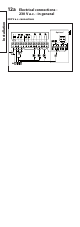
12a Electrical connections 230 V a.c. - in general Installation 230 V a.c.
12b Description 1 L Supply voltage 230 V a.c. 2 N Supply voltage 230 V a.c. 3 M1 Actuator - open Actuator - close 4 M1 alt. thermo actuator 230 V a.c. supply voltage for 5 M1 6 Not to be used. 7 Do not establish any connections! 8 Circulation pump, primary 9 P1 circuit 230 V a.c. supply for pump 10 relay R1 11 P2 DHW charging pump 230 V a.c. supply for pump 12 relay R2 13 P3 DHW circulation pump 230 V a.c. supply for pump 14 relay R3 Max. load 0.2 A / 230 V a.c. 0.2 A / 230 V a.c. 4 (2) A / 230 V a.c.
13a Electrical connections 24 V a.c. - in general Installation 24 V a.c.
b Description Max. load 1 L1 Supply voltage 24 V a.c. 2 L2 Supply voltage 24 V a.c. 3 M1 Actuator - open 1 A / 24 V a.c. Actuator - close 4 M1 1 A / 24 V a.c. alt. thermo actuator 5 24 V a.c. supply voltage for M1 6 Not to be used. 7 Do not establish any connections! 8 9 K1 10 11 K2 12 13 K3 14 Relay for circulation pump, 4 (2) A / 24 V a.c. primary circuit 24 V a.c. supply for K1 Relay for DHW charging pump 4 (2) A / 24 V a.c. 24 V a.c. supply for K2 Relay for DHW circulation 4 (2) A / 24 V a.c.
a Connecting and placing the temperature sensors Installation Connecting the temperature sensors and the bus Terminal Description 15 and 16 Type (recomm.
14b The temperature sensor mentioned below are sensors used for the ECL Comfort 200 and 300 series which not all will be needed for your application! Outdoor temperature sensor (ESMT) The outdoor sensor should be mounted on that side of the building where it is less likely to be exposed to direct sunshine. It should not be placed close to doors, windows or air outlets. Flow temperature sensor (ESMU, ESM-11 or ESMC) Place the sensor max. 15 cm from the mixing point.
14c Installation Override For an active override, you have to choose the mode “scheduled operation”! Input S1 ... S6 (ECL Card C14 only uses S5) can be used for override purposes (section 32, line 141).
14c Installation
Inserting the ECL Card Installation 15a How to insert your ECL Card the first time After the power has been switched on, open the lid on the front side of the controller. Place the ECL Card with the yellow side facing you. This enables the controller to read the ECL Card data. The controller immediately starts to copy the application type and factory settings from the ECL Card. After copying, the display will show you the application type. After approx. 10 sec. the display will change to display line C.
15b The ECL Card contains factory settings for a standard system. If the actual system differs from the standard system, the controller must be adjusted accordingly. After the adjustment, the new settings should be stored on the ECL Card. For ECL Card copying and daily use including adjustment of temperatures and schedules, insert the ECL Card with the yellow side facing you. For system set-up adjustments, the grey side of the ECL Card - the installer’s side - must be facing you.
16 Adjusting the ECL Card settings General principles When the controller is connected and operating you can check and adjust all or some of the basic settings. Turn the ECL Card so that the grey side is facing you (see the example below). Use the arrow buttons to move from line to line of the ECL Card, for example line 2: 1 ON Basic set-up Circuit Line 1 2 2 ON 3 ON 2 Setting to be adjusted 40 90 Value in range indicator Use the plus / minus buttons to adjust the settings.
17 Setting the time and date line A Actual time A 1035 Year 108 0527 Month, day Use the shift button to switch between minutes, hours, years, months and days. Set the correct time and date. Use the yellow side of the card to change the schedules. See User’s Guide, section 4. The grey side of the ECL Card Basic set-up In case of a power break, which lasts longer than 12 hours, the time and the date have to be set again. All other settings are stored as programmed.
18 Monitoring temperatures and system units - line B Controlled units 1 B DHW charging temp. (S2) 1 2 3 ON ON 62 59 DHW temp. (S3) Basic set-up Push and hold the shift button to see: - the desired DHW charging temperature - the desired DHW temperature. The activity of the motorized control valve is shown as arrows below the valve symbol. When the circulation pump is operating, it is indicated as ON below the pump symbol.
19 Manual control line B Shift to manual mode. Controlled units 1 B ON 62 1 2 3 Controller mode ON 59 Choose the unit you want to control. The selected unit symbol will blink. OFF or ON when The motorized actuator (gear motor) closes or opens the controlled unit as long as the relevant button is pushed. If pushed for more than 3 seconds, the actuator continues to close or open the valve. The thermo actuator activates the valve as long as the button is pushed.
20a Monitoring temperatures and system units - line B (circuit II) Choose circuit II for the readout of the supply and return temperatures. 1 B Basic set-up Supply temp. (S1) The grey side of the ECL Card ON 80 1 2 3 ON ON 33 Return temp.
20b Basic set-up The grey side of the ECL Card
a 4 Control parameters lines 4-7 Proportional band, Xp Circuit Setting range Factory setting I 1 ... 250 K 80 / 180 K 1 ON Line Xp1 4 1 2 3 ON ON 80 80 Setting to be adjusted 1 80 Xp2 Basic set-up Set the proportional band. A higher value will result in a stable but slow control of the flow temperature. If you want to adjust the Xp1 and Xp2, push the shift button once or twice. Xp Xp 2 Xp1 65 90 oC S1 - T supply Xp is a function of the supply temperature (sensor S1).
26b 7 Neutral zone, Nz Circuit Setting range Factory setting I 0 ... 9 K 3K Set the neutral zone to a high value if you can accept a high variation in flow temperature. When the actual flow temperature is within the neutral zone, the controller does not activate the motorized valve. Control parameters (lines 4-7) are overruled if thermo actuator is chosen (OFF). If you want to tune the PI regulation precisely, you can use the following method: • Set the integration time (line 5) to its max.
27a Cut-in and cut-out temperature at DHW charging - lines 1-2 The controller can control the DHW temperature with either one or two tank temperature sensor(s). The controller will automatically register the number of sensors. 1 Cut-out temperature difference - (lower sensor)* Circuit Setting range Factory setting I 1 ... 99 K 15 K Set the difference between the desired charging temperature and cut-out temperature (charging stop) . Basic set-up Set the difference.
27b One sensor (S6) Temp. Cut-out difference - line 1 Cut-in difference - line 2 S6 Cut-in Cut-out Charging temperature Time P2 Two sensors (S5 + S6) Temp. Cut-out difference - line 1 Cut-in difference - line 2 S6 Cut-in Cut-out S5 Charging temperature Time P2 The DHW temperature will vary between the cut-in and the cutout temperatures.
29a Check list Is the ECL Comfort controller ready for use? Make sure that the correct power supply is connected to terminals 1 (Live) and 2 (Neutral). See section 12 or 13. Check that the required actuators, pumps, fans, dampers and burners are connected to the correct terminals. See sections 12 or 13. Check that all sensors are connected to the correct terminals. See section 14. Mount the controller and switch on the power. Insert the ECL Card with the yellow side facing you and push , if necessary.
29b Adapting the ECL Comfort controller to the system Turn the ECL Card so that the grey side faces you and push , if necessary. Set the time and the date (line A). See section 17. Check that all settings in the controller (sections 30 and 31) are set or that the factory settings comply with your requirements. If your system differs from the diagram shown on the cover, you should check and alter your service parameters, if necessary.
30 ECL Card settings A Time and date Section 17 B System information Sections 18 & 19 C Setting ranges Factory settings 1 Cut-out temperature difference 1 ... 99 K 15 K See section 27 Control & overviews 2 Cut-in temperature difference 1 ... 99 K 20 K See section 27 3 4 Proportional band, Xp 1 ... 250 K 80 / 180 K See section 26 5 Integration time, Tn 5 ... 999 sec. 30 sec. See section 26 6 Running time of the motorized control valve 5 ... 250 sec. 35 sec.
30b ECL Card settings (circuit II) A Time and date B System information Section 17 Sections 18 & 19 C Setting ranges Factory settings Your settings 1 2 4 5 6 7 Control & overviews 3
31a Service parameters (10-199) Control & overviews Circuit I (DHW) Lines Setting ranges Factory settings 22 Pump exercise ON / OFF ON 23 Valve exercise ON / OFF ON 24 Gear motor / thermo actuator ON / OFF ON 30 Return temperature limitation, S4 10 ... 110 °C 60 °C 35 Return temperature influence, max. -9.9 ... 0 ... 9.9 0.0 36 Return temperature influence, min. -9.9 ... 0 ... 9.9 0.0 37 Time constant for return temperature limitation OFF / 1 ... 50 25 40 DHW charging pump post-run (P2) 0 ... 9 min.
Service parameters (10-199) Circuit I (DHW) Lines Setting ranges Factory settings 174 Motor protection OFF / 10 ... 59 min. 196 Service pin LON ON / OFF 197 LON reset ON / OFF 198 Daylight saving time changeover ON / OFF 199 Master / slave address 0 ... 9, 15 OFF 31b Your settings min.
32 Adjusting the service parameters In addition to the settings in line 1 to 7 on the grey side of the ECL Card, there is an extended service menu from line 10 and onwards. Push repeatedly to reach the lines numbered 10 and onwards. 0 Value 10 Line Range indicator Now you can move to any line of your choice. Set the parameter value. You can select any of the two circuits no matter what line you are in. You will not necessarily enter the same line number. See the service parameters in section 31.
32a Service parameter(s) 22-30 22 Pump exercise Circuit Setting range Factory setting I ON / OFF ON Exercises the pump to avoid blocking in periods without cooling demand. ON: The pump is switched ON for 1 minute every third day around noon. OFF: The pump exercise is not active. 23 Valve exercise Circuit Setting range Factory setting I ON / OFF ON Exercises the valve to avoid blocking in periods without heat demand. ON: The valve receives a signal to open and close every third day around noon.
32b Service parameter(s) 35 35 Return temperature influence, max. Circuit Setting range Factory setting I -9.9 ... 0 ... 9.9 0.0 Set the influence from the return temperature on the desired DHW charging temperature. Set the influence of the max. return temperature (set in line 30). Influence higher than 0: The desired DHW charging temperature is increased, when the return temperature gets higher than the set limit.
32c Service parameter(s) 36 36 Return temperature influence - min. limitation Circuit Setting range Factory setting I -9.9 ... 0 ... 9.9 0.0 Set the influence from the return temperature on the desired DHW charging temperature. Set the influence of the min. return temperature limitation (set in line 30 or lines 31-34). Influence higher than 0: The desired DHW charging temperature is increased, when the return temperature gets below the set limit.
32d Service parameter(s) 37-44 37 Time constant for return temperature limitation Circuit Setting range Factory setting I OFF / 1 ... 50 25 Controls how fast the actual return temperature adapts to the desired return temperature limitation. Adjust the time constant for the return limitation. The setting will eliminate the difference between the acceptable and the actual return temperature. The difference is integrated to adjust the desired flow temperature.
32e Service parameter(s) 45-55 45 DHW charging deactivation time Circuit Setting range Factory setting I 0 ... 250 min. 0 min. If the charging time has reached its maximum (line 44), the charging is deactivated for the set time. 0: No deactivation time. 1 ... 250: When the DHW charging time has reached its maximum, DHW can only be charged again when the deactivation time has expired.
32f Service parameter(s) 67 67 Adaptive function of S2 DHW charging temperature during DHW charging Circuit Setting range Factory setting I OFF / 1 ... 50 20 The setting will eliminate the difference between the desired DHW charging temperature (S2) and the DHW temperature (S3) by integrating the difference and adjusting the desired S2 flow temperature. OFF: The desired DHW charging temperature will not be adjusted any further. 1: The desired DHW charging temperature will be adjusted quickly.
Service parameter(s) 78-83 32g 78 Desired temperature for anti-bacteria function Circuit Setting range Factory setting I OFF / 1 ... 100 °C OFF Set the desired temperature for the anti-bacteria function. The DHW will be charged daily or once a week at the set temperature to protect against bacteria. The function is always active on Mondays from 00:00 and the DHW is charged according to the period set in line 80. OFF: The anti-bacteria function is not active. 1 ...
32h Service parameter(s) 141 141 Override input selection Circuit Setting range Factory setting I OFF / 1 ... 6 OFF Choose an unused temperature sensor input for overriding the schedule for circuit I and / or circuit II. The override can be activated for comfort or setback mode. For override the controller's mode must be in 'scheduled operation'! OFF: The controller's schedule is not overridden. 1 ... 6: Select an unused sensor input S1 ... S6 for the override of the circuit in question.
32i Service parameter(s) 147 147 Acceptable temperature deviation below desired DHW charging temperature (ΔT1ALARM) Circuit Setting range Factory setting I OFF / 1 ... 30 K OFF The alarm is activated if the actual DHW charging temperature drops too much below the desired temperature. The max. deviation ΔT1ALARM is set here. This condition must last longer than the time interval ΔtALARM (line 149). See also line 148.
32j Service parameter(s) 148 148 Acceptable temperature deviation above the desired DHW charging temperature (ΔT2ALARM) Circuit Setting range Factory setting I 1 ... 30 K 5K The alarm is activated if the actual DHW charging temperature rises too much above the desired temperature. The max. deviation ΔT2ALARM is set here. This condition must last longer than the time interval ΔtALARM (line 149). This alarm can only be activated if the value in line 147 is set to 1 ... 30 K. 1 ...
32k Service parameter(s) 149-152 149 Time interval ΔtALARM before activation of alarm function Circuit Setting range Factory setting I 1 ... 99 min. 10 min. If an alarm condition from either line 147 or 148 is present for a longer time than the time interval ΔtALARM , the alarm function is activated. 1 ... 99: Time interval ΔtALARM. Temp. Actual temp. (S2) Line 148 Desiredtemp.
32l Service parameter(s) 174-198 174 Motor protection Circuit Setting range Factory setting I OFF / 10 ... 59 min. OFF Prevents the controller from unstable temperature control (and resulting actuator oscillations). This can occur when there is no DHW tapping, i.e. when the load is only due to the DHW circulation, or when the heating demand in the heating circuit is very low. The motor protection increases the lifetime of all involved components. OFF: Motor protection is not activated. 10 ...
Service parameter(s) 199 32m 199 Master / slave address Circuit Setting range Factory setting I 0 ... 9, 15 15 The setting is relevant when more controllers are working in the same ECL Comfort system (connected via the system device bus (ECL Comfort BUS)). 0: The slave receives information about the system time. 1 ... 9: The slave receives information about the system time. The slave sends information about the desired flow temperature (at S2) to the master. 15: The controller is master.
34a Copying with the ECL Card Check the ECL Card and the software generations (see following example). Insert the ECL Card with the yellow side facing you. Go to line 8 (is not displayed), which is the first line below line 7. Application type C37 Software version, ECL Card 05 109 Software version, controller Store new controller settings on the ECL Card All new settings* can be stored on the ECL Card. Insert the ECL Card with the yellow side facing you.
34b Copy personal settings to additional controller(s) in identical systems Ensure that the other controller(s) use(s) the same ECL Card type. (If this is not the case, please read section 15). Insert the ECL Card, which contains the personal settings, with the yellow side facing you. Go to line 9 (is not displayed), which is the second line below line 7. Select the copying direction (from the card to the controller). CPY Card 0 C99 Controller Copying direction Copy.
7a Definitions Air duct temperature Temperature measured in the air duct where the temperature is to be controlled. Balance temperature This setpoint is the basis for the flow / air duct temperature. The balance temperature can be adjusted by the room temperature, the compensation temperature and the return temperature. The balance temperature is only active if a room temperature sensor is connected. Comfort operation Normal temperature in the system controlled by the schedule.
7b Humidity, relative This value (stated in %) refers to the indoor moisture content compared to the max. moisture content. The relative humidity is measured by the ECA 62 / 63 and is used for the calculation of the dew point temperature. Limitation temperature Temperature that influences the desired flow / balance temperature. Pt 1000 sensor All sensors used with the ECL Comfort controller are based on the Pt 1000 type. The resistance is 1000 ohm at 0 °C and it changes with 3.9 ohm / degree.
6a Hot points The time shown in the display is one hour off? See the summer time changeover in line 198, section 32. The time shown in the display is not correct? The internal clock may have been reset, if there has been a power break for more than 12 hours. Set time and date. See section 17. The ECL Card is lost? Switch the power off and on again to see the system type and the software generation of the controller. Order a replacement from your Danfoss representative.
6b How to make an extra comfort period in the schedule? You can make an additional comfort period by pushing the shift and + buttons simultaneously for 2 seconds. See section 4. How to remove a comfort period in the schedule? You can remove a comfort period by pushing the shift and - buttons simultaneously for 2 seconds. See section 4. How to restore your personal settings? Insert the ECL Card with the yellow side facing you. Go to line 9 (is not displayed), which is the second line below line 7.
5a Advantages of the ECL Card Save your personal settings to the ECL Card Go to line 9 (is not displayed), which is the second line below line 7. CPY 0 Card C99 Controller Copying direction Accept to copy personal settings from the controller to the ECL Card. The controller will return to display line C when the copying is completed. This takes approx. 15 seconds.
5b Restore ECL Card data After establishing your favorite temperatures, comfort periods etc., and after copying these to the ECL Card, you can set alternative settings. Insert the ECL Card and make the temporary settings, e.g. for holidays, but do not copy these. To restore your favorite settings, copy these from the ECL Card to the controller. Insert the ECL Card. Go to line 9 (is not displayed), which is the second line below line 7.
4a Set your personal schedule Monitor the current schedules Select between lines 1-7 (Monday, Tuesday ...... Sunday) to see your individual schedules. Changeover time Line Circuit Time line Periods with comfort temp. are shown as black bars Change the schedules Select appropriate day. The changeover point blinks Adjust the first blinking changeover point, if required. The end of the bar moves, extending or reducing the comfort period. Shift to next changeover point and adjust accordingly.
4b Add an extra comfort period Push the shift and + button simultaneously for 2 seconds. The new period appears Adjust the new period. Remove a comfort period Select the period to be removed (blinking changeover point) Push shift and - buttons simultaneously for 2 seconds. Cancel changes in your personal settings Push - and + buttons simultaneously for 2 seconds to restore the factory settings of the actual schedule.
2 Select circuit mode During scheduled operation (clock), the state indicator (a white arrow) will show you the control mode of the selected circuit. The mode can be set differently for each circuit by means of the function selector. However, if manual operation (hand) is chosen, this mode will apply to all circuits. Function selector (black arrow) State indicator (white arrow) 20 Function selector. Push the button to change the mode of the circuit.
3 Set your DHW charging temperature Choose the display C for daily operations. Circuit I: Setting the desired DHW charging temperature 55 Desired DHW temp. in comfort mode 10 Desired DHW temp. in setback mode Select the constant comfort mode. Set the desired DHW temperature for the comfort mode. Select the constant setback mode. Set the desired DHW temperature for the setback mode. Select the desired mode (section 2).
1a Choose your favorite display (circuit I) Choose the display - A, B, or C - for daily operations. DHW temperature - display A Upper tank temp. (S6) Line A Circuit 56 50 Lower tank temp. (S5) System information - display B State of controlled units Line 1 1 B ON 2 3 ON ON Circuit DHW charging temp. (S2) 62 59 DHW temp. (S3) Push and hold the shift button to see: - the desired DHW charging temperature - the desired DHW temperature.
1b Choose your favorite display (schedule II) Choose the display - A, B, or C - for daily operations. Display A Line A Circuit System information - display B State of controlled units Line 2 3 ON ON 1 1 B ON Circuit 80 Supply temp. (S1) 33 Return temp. (S4) Today’s schedule - display C Time Line Circuit C 1835 0 3 6 9 12 15 18 21 24 Today's schedule The controller automatically reverts to display C if the card has been reinserted or the power supply has been interrupted.
Save energy - save money - improve your comfort temperature The ECL Comfort controller is designed by Danfoss for the automatic temperature control of heating, hot-water, ventilation and cooling systems. Some of the advantages of the ECL Comfort controller system are: • Secure control and the optimum use of energy resources. • Control of system temperatures according to seasonal changes and variations in outdoor temperatures.
Table of Contents Daily use Section 1 Choose your favorite display 2 Select circuit mode 3 Set your DHW charging temperature 4 Set your personal schedule 5 Advantages of the ECL Card 6 Hot points 7 Definitions The documentation for the ECL Comfort controller is composed of numbered sections. Only sections that are relevant to your ECL Comfort controller are included here. Installer's Guide: Grey sections 10 and onwards. Turn the guide over.