
User`s guide
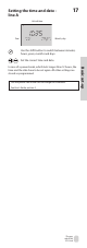


The grey
side of the
ECL Card
Basic set-up
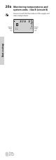
Control parameters -
lines 4-7
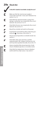
26a
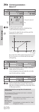
4 Proportional band, Xp
Circuit Setting range Factory setting
I 1 ... 250 K 80 / 180 K
Line
Xp
1
0
4
8
0 081
1
3
ON
2
ON
1
ON
8
Setting to be adjusted
Xp
2
Set the proportional band.
A higher value will result in a stable but slow
control of the ow temperature.
If you want to adjust the Xp
1
and Xp
2
, push the
shift button once or twice.
65 90
Xp
Xp
Xp
C
o
2
1
Xp is a function of the supply temperature (sensor
S1). If a S1 sensor is not connected, the Xp value
will equal Xp
1
.
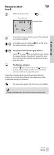
5 Integration time, Tn
Circuit Setting range Factory setting
I 5 ... 999 sec. 30 sec.
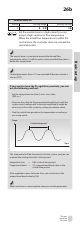
Set a long integration time to obtain a slow but
stable reaction to deviations.
A short integration time will make the controller
react fast but with less stability
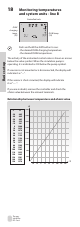
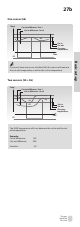
6 Running time of the motorized control valve
Circuit Setting range Factory setting
I 5 ... 250 sec. 35 sec.
Set the running time of the motorized control
valve according to the example. This is the time it
takes the controlled unit to move from fully closed
to fully open position.
How to calculate the running time of a motorized
control valve
The running time of the motorized control valve is calculated
using the following methods:
Seated valves
Running time = Valve stroke (mm) x actuator speed (sec. / mm)
Example: 5.0 mm x 15 sec. / mm = 75 sec.
Rotating valves
Running time = Turning degrees x actuator speed (sec. / degr.)
Example: 90 degrees x 2 = 180 sec.
S1 - T supply