Installation Guide ECL Comfort 210 / 310, application A231 / A331 1.0 Table of Contents 1.0 Table of Contents ............................................... 1 6.0 Common controller settings.............................. 85 1.1 6.1 6.2 6.3 6.4 6.5 6.6 6.7 6.8 Important safety and product information. . . . . . . . . . . . . . . . . . . . . 2 2.0 Installation ........................................................ 4 2.1 2.2 2.3 2.4 2.5 2.6 2.7 2.8 Before you start . . . . . . . . . . . . . . . . . .
Installation Guide ECL Comfort 210 / 310, application A231 / A331 1.1 Important safety and product information 1.1.1 Important safety and product information This Installation Guide is associated with ECL Application Key A231 (order code no. 087H3805). The A231 Key contains two sets of applications: one set (A231.1 / A231.2) and another set (A331.1 / A331.2). The functions can be realized in: ECL Comfort 210 (A231) for simple solutions or ECL Comfort 310 (A231 / A331) for e.g.
Installation Guide ECL Comfort 210 / 310, application A231 / A331 The ID no. is unique for the selected parameter. Example First digit Second digit Last three digits 11174 1 1 174 - Circuit 1 Parameter no. 1 2 174 - Circuit 2 Parameter no. 12174 If an ID description is mentioned more than once, it means that there are special settings for one or more system types. It will be marked with the system type in question (e.g. 12174 - A266.9).
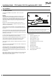
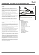
Installation Guide ECL Comfort 210 / 310, application A231 / A331 2.0 Installation 2.1 Before you start The application A231.1 is very flexible. These are the basic principles: Typical A231.1 application: Da nfos s 87H2006.10 ECL 210 S1 Heating: Typically, the flow temperature is adjusted according to your requirements. The flow temperature sensor S3 is the most important sensor. The desired flow temperature at S3 is calculated in the ECL controller, based on the outdoor temperature (S1).
ECL Comfort 210 / 310, application A231 / A331 Application A231.1 in general: Typical A231.1 application: The circulation pumps P1 and P2 work in shift according to a schedule. One pump is used as spare pump and the other pump is working. In case of malfunction (missing differential pressure) of one pump, the other pump will take over. An alarm will be generated and the defective pump can be inspected / repaired.
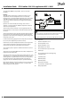
ECL Comfort 210 / 310, application A231 / A331 The application A231.2 is very flexible. These are the basic principles: Typical A231.2 application: ECL 210 S1 Heating: Typically, the flow temperature is adjusted according to your requirements. The flow temperature sensor S3 is the most important sensor. The desired flow temperature at S3 is calculated in the ECL controller, based on the outdoor temperature (S1). The lower the outdoor temperature, the higher the desired flow temperature.
ECL Comfort 210 / 310, application A231 / A331 Application A231.2 in general: Typical A231.2 application: The circulation pumps P1 and P2 work in shift according to a schedule. One pump is used as spare pump and the other pump is working. In case of malfunction (missing differential pressure) of one pump, the other pump will take over. An alarm will be generated and the defective pump can be inspected / repaired.
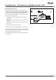
ECL Comfort 210 / 310, application A231 / A331 The application A331.1 is very flexible. These are the basic principles: Typical A331.1 application: ECL 310 S1 Heating: Typically, the flow temperature is adjusted according to your requirements. The flow temperature sensor S3 is the most important sensor. The desired flow temperature at S3 is calculated in the ECL controller, based on the outdoor temperature (S1). The lower the outdoor temperature, the higher the desired flow temperature.
ECL Comfort 210 / 310, application A231 / A331 Application A331.1 in general: Typical A331.1 application: The circulation pumps P1 and P2 work in shift according to a schedule. One pump is used as spare pump and the other pump is working. In case of malfunction (missing differential pressure) of one pump, the other pump will take over. An alarm will be generated and the defective pump can be inspected / repaired. ECL 310 S1 Da nfos s 87H2003.
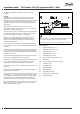
ECL Comfort 210 / 310, application A231 / A331 The application A331.2 is very flexible. These are the basic principles: Typical A331.2 application: Heating: Typically, the flow temperature is adjusted according to your requirements. The flow temperature sensor S3 is the most important sensor. The desired flow temperature at S3 is calculated in the ECL controller, based on the outdoor temperature (S1). The lower the outdoor temperature, the higher the desired flow temperature.
ECL Comfort 210 / 310, application A231 / A331 Application A331.2 in general: Typical A331.2 application: The circulation pumps P1 and P2 work in shift according to a schedule. One pump is used as spare pump and the other pump is working. In case of malfunction (missing differential pressure) of one pump, the other pump will take over. An alarm will be generated and the defective pump can be inspected / repaired. ECL 310 S1 Da nfos s 87H2004.
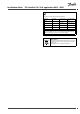
Installation Guide ECL Comfort 210 / 310, application A231 / A331 2.2 Identifying the system type Sketch your application The ECL Comfort controller series is designed for a wide range of heating, domestic hot-water (DHW) and cooling systems with different configurations and capacities. If your system differs from the diagrams shown here, you may want to make a sketch of the system about to be installed.
Installation Guide ECL Comfort 210 / 310, application A231 / A331 A231.2 Indirectly connected heating system with two-pump control and refill water function (supply temperature measurement gives further control / limitation possibilities): Da nfos s 87H2005.10 ECL 210 S1 R4 P S7 S2 S3 P1 P2 S5 M1 S8 V1 P3 A331.1 Indirectly connected heating system with two-pump control and refill water function: Da nfos s 87H2003.10 ECL 310 S1 R6 S9 P S7 S 10 S3 P1 P2 S5 M1 S8 V1 P3 P5 A331.
Installation Guide ECL Comfort 210 / 310, application A231 / A331 2.3 Mounting 2.3.1 Mounting the ECL Comfort controller For easy access, you should mount the ECL Comfort controller near the system. Select one of the following methods using the same base part (code no. 087H3220): • Mounting on a wall • Mounting on a DIN rail (35 mm) The ECL Comfort 310 is to be mounted in the ECL Comfort 310 base part. Screws, PG cable glands and rawlplugs are not supplied.
Installation Guide ECL Comfort 210 / 310, application A231 / A331 Mounting on a DIN rail (35 mm) Mount the base part on a DIN rail. Establish the electrical connections and position the controller in the base part. Secure the controller with the locking pin. Dismounting the ECL Comfort controller In order to remove the controller from the base part, pull out the locking pin by means of a screwdriver. The controller can now be removed from the base part. Danfoss District Energy VI.LG.P1.
Installation Guide ECL Comfort 210 / 310, application A231 / A331 2.3.2 Mounting the Remote Control Units ECA 30/31 Select one of the following methods: • Mounting on a wall, ECA 30 / 31 • Mounting in a panel, ECA 30 Screws and rawlplugs are not supplied. Mounting on a wall Mount the base part of the ECA 30 / 31 on a wall with a smooth surface. Establish the electrical connections. Place the ECA 30 / 31 in the base part.
Installation Guide ECL Comfort 210 / 310, application A231 / A331 2.4 Placing the temperature sensors 2.4.1 Placing the temperature sensors It is important that the sensors are mounted in the correct position in your system.
Installation Guide ECL Comfort 210 / 310, application A231 / A331 Pt 1000 temperature sensor (IEC 751B, 1000 Ω / 0 °C) Relationship between temperature and ohmic value: Ω °C Ω -50 -40 -30 -20 -10 0 10 20 30 40 50 60 70 80 90 100 110 120 130 140 150 803 843 882 922 961 1000 1039 1078 1117 1155 1194 1232 1271 1309 1347 1385 1423 1461 1498 1535 1573 1600 1500 1400 1300 1200 1100 1000 900 800 °C -50 18 DEN-SMT/DK VI.LG.P1.
Installation Guide ECL Comfort 210 / 310, application A231 / A331 2.5 Electrical connections 2.5.1 Electrical connections 230 V a.c. in general The common ground terminal is used for connection of relevant components (pumps, motorized control valves). Danfoss District Energy VI.LG.P1.
Installation Guide ECL Comfort 210 / 310, application A231 / A331 2.5.2 Electrical connections, 230 V a.c., power supply, pumps, motorized control valves etc. Application A231.1 / A231.2 Terminal 16 15 14 Description Max. load Alarm 4 (2) A / 230 V a.c.* Phase for circulation pumps and refill water pump 13 P3 Refill water pump ON / OFF 4 (2) A / 230 V a.c.* 12 P2 Circulation pump ON / OFF 4 (2) A / 230 V a.c.* 11 P1 Circulation pump ON / OFF 4 (2) A / 230 V a.c.
Installation Guide ECL Comfort 210 / 310, application A231 / A331 Application A331.1 / A331.2 Terminal Description 19 Phase for refill water pump and alarm 18 Alarm 4 (2) A / 230 V a.c.* Refill water pump ON / OFF 4 (2) A / 230 V a.c.* 17 P5 16 Do not use 15 Do not use 14 Phase for circulation pumps Max. load 13 P3 Refill water pump ON / OFF 4 (2) A / 230 V a.c.* 12 P2 Circulation pump ON / OFF 4 (2) A / 230 V a.c.* 11 P1 Circulation pump ON / OFF 4 (2) A / 230 V a.c.
Installation Guide ECL Comfort 210 / 310, application A231 / A331 Wire cross section: 0.5 - 1.5 mm² Incorrect connection can damage the electronic outputs. Max. 2 x 1.5 mm² wires can be inserted into each screw terminal. 22 DEN-SMT/DK VI.LG.P1.
Installation Guide ECL Comfort 210 / 310, application A231 / A331 2.5.3 Electrical connections, safety thermostats, 230 V a.c. or 24 V a.c. With safety thermostat, ECL Comfort 210: With safety thermostat, ECL Comfort 310: Wire cross section: 0.5 - 1.5 mm² Incorrect connection can damage the electronic outputs. Max. 2 x 1.5 mm² wires can be inserted into each screw terminal. Danfoss District Energy VI.LG.P1.
Installation Guide ECL Comfort 210 / 310, application A231 / A331 2.5.4 Electrical connections, 24 V a.c., power supply, pumps, motorized valves etc. Application A231.1 / A231.2 Terminal 16 15 14 Description Max. load Alarm 4 (2) A / 24 V a.c.* Phase for circulation pumps and refill water pump 13 K3 Refill water pump ON / OFF 4 (2) A / 24 V a.c.* 12 K2 Circulation pump ON / OFF 4 (2) A / 24 V a.c.* 11 K1 Circulation pump ON / OFF 4 (2) A / 24 V a.c.* 10 Supply voltage 24 V a.c.
Installation Guide ECL Comfort 210 / 310, application A231 / A331 Do not connect 230 V a.c. powered components to a 24 V a.c. power supplied controller directly. Use auxilliary relays (K) to seperate 230 V a.c. from 24 V a.c. Danfoss District Energy VI.LG.P1.
Installation Guide ECL Comfort 210 / 310, application A231 / A331 Application A331.1 / A331.2 Terminal Description 19 Phase for refill water pump and alarm 18 Alarm 4 (2) A / 24 V a.c.* Refill water pump ON / OFF 4 (2) A / 24 V a.c.* 17 K5 16 Do not use 15 Do not use 14 Phase for circulation pumps Max. load 13 K3 Refill water pump ON / OFF 4 (2) A / 24 V a.c.* 12 K2 Circulation pump ON / OFF 4 (2) A / 24 V a.c.* 11 K1 Circulation pump ON / OFF 4 (2) A / 24 V a.c.
Installation Guide ECL Comfort 210 / 310, application A231 / A331 Wire cross section: 0.5 - 1.5 mm² Incorrect connection can damage the electronic outputs. Max. 2 x 1.5 mm² wires can be inserted into each screw terminal. Do not connect 230 V a.c. powered components to a 24 V a.c. power supplied controller directly. Use auxilliary relays (K) to seperate 230 V a.c. from 24 V a.c. Danfoss District Energy VI.LG.P1.
Installation Guide ECL Comfort 210 / 310, application A231 / A331 2.5.5 Electrical connections, Pt 1000 temperature sensors and signals A231.1 / A231.2: Terminal Sensor / description 29 and 30 S1 28 and 30 S2 27 and 30 S3 25 and 30 S5 23 and 30 S7 22 and 30 S8 Type (recomm.
Installation Guide ECL Comfort 210 / 310, application A231 / A331 Connection of a pressure transmitter with 4-20 mA output The 4-20 mA signal is converted to a 2-10 V signal by means of the 500 ohm resistor. Connection of a pressure switch P A331.1 / A331.2: Terminal Sensor / description 29 and 30 S1 28 and 30 S2 27 and 30 S3 25 and 30 S5 23 and 30 S7 22 and 30 S8 21 and 30 S9 Type (recomm.
Installation Guide ECL Comfort 210 / 310, application A231 / A331 Connection of differential pressure switch Connection of a pressure transmitter with 0-10 V output Example of a pressure transmitter connection to S10. Pressure transmitter can be connected in the same way to S8. Connection of a pressure transmitter with 4-20 mA output The 4-20 mA signal is converted to a 2-10 V signal by means of the 500 ohm resistor. Example of a pressure transmitter connection to S10.
Installation Guide ECL Comfort 210 / 310, application A231 / A331 Wire cross section for sensor connections: Min. 0.4 mm². Total cable length: Max. 200 m (all sensors incl. internal ECL 485 communication bus) Cable lengths of more than 200 m may cause noise sensibility (EMC). Danfoss District Energy VI.LG.P1.
Installation Guide ECL Comfort 210 / 310, application A231 / A331 2.5.6 Electrical connections, ECA 30 / 31 Terminal Terminal Description ECL 310 ECA 30 / 31 4 30 Twisted pair 1 31 32 2 33 3 4 5 Type (recomm.) Cable 2 x twisted pair Twisted pair Ext. room temperature sensor* ESM-10 * After an external room temperature sensor has been connected, ECA 30 / 31 must be repowered. The communication to the ECA 30 / 31 must be set up in the ECL Comfort controller in 'ECA addr.
Installation Guide ECL Comfort 210 / 310, application A231 / A331 2.5.7 Electrical connections, master / slave systems The controller can be used as master or slave in master / slave systems via the internal ECL 485 communication bus (2 x twisted pair cable).
Installation Guide ECL Comfort 210 / 310, application A231 / A331 2.6 Inserting the ECL Application Key 2.6.1 Inserting the ECL Application Key The ECL Application Key contains • the application and its subtypes, • currently available languages, • factory settings: e.g. schedules, desired temperatures, limitation values etc. It is always possible to recover the factory settings, • memory for user settings: special user / system settings.
Installation Guide ECL Comfort 210 / 310, application A231 / A331 Application Key: Situation 1 The controller is new from the factory, the ECL Application Key is not inserted. An animation for the ECL Application Key insertion is displayed. Insert the Application Key . Application Key name and Version is indicated (example: A266 Ver. 1.03). If the ECL Application Key is not suitable for the controller, a "cross" is displayed over the ECL Application Key-symbol.
Installation Guide ECL Comfort 210 / 310, application A231 / A331 Application Key: Situation 2 The controller already runs an application. The ECL Application Key is inserted, but the application needs to be changed. To change to another application on the ECL Application Key, the current application in the controller must be erased (deleted). Be aware that the Application Key must be inserted.
Installation Guide ECL Comfort 210 / 310, application A231 / A331 Application Key: Situation 3 A copy of the controllers settings is needed for configuring another controller. This function is used • for saving (backup) of special user and system settings • when another ECL Comfort controller of the same type (210 or 310) must be configured with the same application but user / system settings differ from the factory settings.
Installation Guide ECL Comfort 210 / 310, application A231 / A331 2.6.2 ECL Application Key, copying data General principles When the controller is connected and operating, you can check and adjust all or some of the basic settings. The new settings can be stored on the Key. Factory settings can always be restored. How to update the ECL Application Key after settings have been changed? All new settings can be stored on the ECL Application Key.
Installation Guide ECL Comfort 210 / 310, application A231 / A331 2.7 Check list Is the ECL Comfort controller ready for use? Make sure that the correct power supply is connected to terminals 9 (Live) and 10 (Neutral). Check that the required controlled components (actuator, pump etc.) are connected to the correct terminals. Check that all sensors / signals are connected to the correct terminals (see 'Electrical connections'). Mount the controller and switch on the power.
Installation Guide ECL Comfort 210 / 310, application A231 / A331 2.8 Navigation, ECL Application Key A231 / A331 Navigation, application A231.1 / A331.1 Home Heating ID no. Function MENU Schedule Settings Selectable Heat curve Flow temperature 11178 Return limit Temp. min. 11031 High T out X1 11032 Low limit Y1 11033 Low T out X2 11034 High limit Y2 11035 Infl. - max. 11036 Infl. - min. 11037 Adapt. time 11085 Priority Flow / power limit Actual Optimization Control par.
Installation Guide ECL Comfort 210 / 310, application A231 / A331 Navigation, applications A231.1 / A331.1, continued Home MENU Settings Heating Pump control ID no. 11314 Function Chan.-over time 11310 Retry time 11313 Stab. time 11311 Change, duration 11312 Change time 11022 Application 11327 Input type 11323 Time-out 11321 Pressure, des. 11322 Pressure, diff. 11320 P exercise 11325 Valve delay 11326 No.
Installation Guide ECL Comfort 210 / 310, application A231 / A331 Navigation, application A231.1 / A331.1, Common controller settings (* application A331.1 only) Home MENU Time & Date Settings* Input overview Log (sensors) ID no. Supply pressure* Outdoor T Heating flow & des.
Installation Guide ECL Comfort 210 / 310, application A231 / A331 Navigation, application A231.2 / A331.2 Home Heating ID no. Function MENU Schedule Settings Selectable Heat curve Flow temperature Temp. max. Return limit 11177 Temp. min. 11300 High supp. T X2 11301 High T max Y2 11302 Low supply T X1 11303 Low T max Y1 11031 High T out X1 11032 Low limit Y1 11033 Low T out X2 11034 High limit Y2 11035 Infl. - max. 11036 Infl. - min. 11037 Adapt.
Installation Guide ECL Comfort 210 / 310, application A231 / A331 Navigation, application A231.2 / A331.2, continued Home MENU Settings Heating Pump control ID no. 11314 Function Chan.-over time 11310 Retry time 11313 Stab. time 11311 Change, duration 11312 Change time 11022 P exercise Pressure Refill water Application 11327 Input type 11323 Time-out 11321 Pressure, des. 11322 Pressure, diff. 11320 P exercise 11325 Valve delay 11326 No.
Installation Guide ECL Comfort 210 / 310, application A231 / A331 Navigation, application A231.2 / A331.2, Common controller settings (* application A331.2 only) Home MENU Time & Date Settings* Input overview Log (sensors) ID no. Supply pressure* Outdoor T Supply T Heating flow & des.
Installation Guide ECL Comfort 210 / 310, application A231 / A331 3.0 Daily use 3.1 How to navigate You navigate in the controller by turning the dial left or right to the desired position ( ). The dial has a built-in accellerator. The faster you turn the dial, the faster it reaches the limits of any wide setting range. The position indicator in the display ( ) will always show you where you are. Push the dial to confirm your choices ( ).
Installation Guide ECL Comfort 210 / 310, application A231 / A331 3.2 Understanding the controller display Choosing a favorite display Your favorite display is the display you have chosen as the default display. The favorite display will give you a quick overview of the temperatures or units that you want to monitor in general. If the dial has not been activated for 20 min., the controller will revert to the overview display you have chosen as favorite.
Installation Guide ECL Comfort 210 / 310, application A231 / A331 Setting the desired temperature Depending on the chosen circuit and mode, it is possible to enter all daily settings directly from the overview displays (see also the next page concerning symbols). Setting the desired room temperature The desired room temperature can easily be adjusted in the overview displays for the heating circuit. Action: Purpose: Desired room temperature Examples: 20.
Installation Guide ECL Comfort 210 / 310, application A231 / A331 3.3 What do the symbols mean? Symbol Description Symbol Description Sensor not connected or not used Outdoor temp. Sensor connection short-circuited Room temp. Temperature 7-23 Fixed comfort day (holiday) DHW temp.
Installation Guide ECL Comfort 210 / 310, application A231 / A331 3.4 Monitoring temperatures and system components Heating circuit The overview display in the heating circuit ensures a quick overview of the actual and (desired) temperatures as well as the actual state of the system components.
Installation Guide ECL Comfort 210 / 310, application A231 / A331 3.5 Manual control It is possible to manually control the installed components. Manual control can only be selected in favorite displays in which the symbols for the controlled components (valve, pump etc.) are visible. Action: Purpose: Examples: Choose mode selector Confirm Controlled components Choose manual mode Circuit selector Confirm Choose pump Confirm Switch ON the pump Switch OFF the pump.
Installation Guide ECL Comfort 210 / 310, application A231 / A331 3.6 Schedule 3.6.1 Set your schedule The schedule consists of a 7-day week: M = Monday T = Tuesday W = Wednesday T = Thursday S = Friday = Saturday S = Sunday F The schedule will day-by-day show you the start and stop times of your comfort periods (heating / DHW circuits).
Installation Guide ECL Comfort 210 / 310, application A231 / A331 4.0 Settings overview It is recommendable to make a note of any changed settings in the empty columns. Setting ID Factory settings in circuit(s) Page 1 Temp. max. (flow temp. limit, max.) — A231.1 / A331.1 11178 Temp. min. (flow temp. limit, min.) 11177 56 90 °C 56 10 °C Heat curve 57 Temp. max. (flow temp. limit, max.) — A231.2 / A331.2 58 11177 58 10 °C High supp. T X2 (high value of supply temp.) — A231.2 / A331.
Installation Guide ECL Comfort 210 / 310, application A231 / A331 Setting ID Factory settings in circuit(s) Page 1 Retry time 11310 72 20 m Stab. time (stabilization time) 11313 72 15 s Change, duration 11311 73 2 Change time (changeover time) 11312 73 12 P exercise (pump exercise) 11022 73 OFF 3 74 Pressure 54 2 Input type 11327 75 OFF Time-out 11323 75 20 s Pressure, des. (desired pressure) 11321 75 3.0 bar Pressure, diff. (switching difference) 11322 76 1.
Installation Guide ECL Comfort 210 / 310, application A231 / A331 5.0 Settings, circuit 1 5.1 Flow temperature 5.1.1 A231.1 / A331.1 The ECL Comfort controller determines and controls the flow temperature related to the outdoor temperature. This relationship is called the heat curve. Desired flow temperature °C The heat curve is set by means of 6 coordinate points. The desired flow temperature is set at 6 pre-defined outdoor temperature values.
Installation Guide ECL Comfort 210 / 310, application A231 / A331 Max. limitation of the desired flow temperature: In the applications A231.1 and A331.1 the max. limitation value is selectable in ‘Temp. max.’. Temp. max. (flow temp. limit, max.) — A231.1 / A331.1 11178 Circuit Setting range Factory setting 1 10 ... 150 °C 90 °C The setting for ‘Temp. max.’ has higher priority than ‘Temp. min.’. Set the max. flow temperature for the system.
Installation Guide ECL Comfort 210 / 310, application A231 / A331 5.1.2 A231.2 / A331.2 Desired flow temperature The ECL Comfort controller determines and controls the flow temperature related to the supply temperature (S2). This relationship is set in the controller. °C The heat curve is set in all coordinate points to the max. desired flow temperature (150 °C). The desired flow temperature will always be in relation to the supply temperature (S2).
Installation Guide ECL Comfort 210 / 310, application A231 / A331 Max. limitation of the desired flow temperature: In the application A231.2 / A331.2 the desired flow temperature or max. limitation value depends on the supply temperature (S2). The relationship is set in the four settings ‘High supp. T X2’, ‘High T max Y2’, ‘Low supply T X1’ and ‘Low T max Y1’. When setting the heat curve coordinates as described in the section 'A231.1 / A331.
Installation Guide ECL Comfort 210 / 310, application A231 / A331 Low supply T X1(low value of supply temp.) — A231.2 / A331.2 11302 Circuit Setting range Factory setting 1 10 ... 150 °C 70 °C Set the low value for the supply temperature in relation to the desired max. flow temperature. When the supply temperature is below the set value, the max. limitation of the flow temperature is the Y1 value. When the supply temperature is above the set value, the max.
Installation Guide ECL Comfort 210 / 310, application A231 / A331 5.2 Return limit The return temperature limitation is based on the outdoor temperature. Typically in district heating systems a higher return temperature is accepted at a decrease in outdoor temperature. The relationship between the return temperature limits and outdoor temperature is set in two coordinates. The outdoor temperature coordinates are set in 'High T out X1' and 'Low T out X2'.
Installation Guide ECL Comfort 210 / 310, application A231 / A331 High limit Y2 (return temp. limitation, high limit, Y-axis) 11034 Circuit Setting range Factory setting 1 10 ... 150 °C 60 °C Set the return temperature limitation referring to the outdoor temperature set in 'Low T out X2'. The corresponding X coordinate is set in 'Low T out X2'. Infl. - max. (return temp. limitation - max. influence) 11035 Circuit Setting range Factory setting 1 -9.9 ... 9.9 0.
Installation Guide ECL Comfort 210 / 310, application A231 / A331 11085 Priority (priority for return temp. limitation) Circuit Setting range Factory setting 1 OFF / ON OFF Choose whether the return temperature limitation should overrule the set min. flow temperature ‘Temp. min.’ . 62 ON: The min. flow temperature limit is overruled. OFF: The min. flow temperature limit is not overruled. DEN-SMT/DK VI.LG.P1.
Installation Guide ECL Comfort 210 / 310, application A231 / A331 5.3 Flow / power limit A flow or energy meter can be connected to the ECL controller in order to limit the flow or consumed power. The signal from the flow or energy meter is based on M-bus signal. Flow / power limitation The flow / power limitation can be based on the outdoor temperature. Typically, in district heating systems a higher flow or power is accepted at lower outdoor temperatures.
Installation Guide ECL Comfort 210 / 310, application A231 / A331 11117 Low limit Y1 (flow / power limitation, low limit, Y-axis) Circuit Setting range Factory setting 1 0.0 ... 999.9 l/h 999.9 l/h The limitation function can overrule the set 'Temp. min' of the desired flow temperature. Set the flow / power limitation referring to the outdoor temperature set in 'High T out X1'. The corresponding X coordinate is set in 'High T out X1'.
Installation Guide ECL Comfort 210 / 310, application A231 / A331 11109 Input type, A231 Circuit Setting range Factory setting 1 OFF / EM1 ... EM5 OFF Flow or power limitation is possible in ECL Comfort 310 only. Possible in ECL Comfort 310 only. OFF: No input. EM1: Pulse. 11109 Input type — A331 Circuit Setting range Factory setting 1 OFF / EM1 ... EM5 OFF Flow or power limitation is possible in ECL Comfort 310 only. Choice of M-bus signal from energy meter number 1 ... 5.
Installation Guide ECL Comfort 210 / 310, application A231 / A331 5.4 Optimization Auto saving (saving temp. dependent on outdoor temp.) Reduction 11011 Circuit Setting range Factory setting 1 OFF / -29 ... 10 °C -15 °C Below the set value for the outdoor temperature, the saving temperature setting has no influence. Above the set value for the outdoor temperature, the saving temperature relates to the actual outdoor temperature.
Installation Guide ECL Comfort 210 / 310, application A231 / A331 Temp. °C 11013 Ramp (reference ramping) Circuit Setting range Factory setting 1 OFF / 1 ... 99 m OFF The time (minutes) in which the desired flow temperature increases gradually to avoid load peaks in the heat supply. OFF: The ramping function is not active. Time (min.) 1-99 m: The desired flow temperature is increased gradually with the set minutes.
Installation Guide ECL Comfort 210 / 310, application A231 / A331 11026 Pre-stop (optimized stop time) Circuit Setting range Factory setting 1 OFF / ON ON Example: Optimization of Comfort from 07:00 - 22:00 07:00 22:00 Schedule Disable the optimized stop time. Pre-stop OFF OFF: The optimized stop time is disabled. ON: The optimized stop time is enabled.
Installation Guide ECL Comfort 210 / 310, application A231 / A331 11179 Cut-out (limit for heating cut-out) Circuit Setting range Factory setting 1 OFF / 1 ... 50 °C 20 °C Temp. Actual outdoor temp. Accumulated outdoor temp. 18 °C The heating can be switched OFF when the outdoor temperature is higher than the set value. The valve closes and after the post-run time, the heating circulation pump stops. ‘Temp. min.’ will be overruled.
Installation Guide ECL Comfort 210 / 310, application A231 / A331 5.5 Control parameters 11174 Motor pr. (motor protection) Circuit Setting range Factory setting 1 OFF / 10 ... 59 m OFF Recommended for heating systems with variable load. Prevents the controller from unstable temperature control (and resulting actuator oscillations). This can occur at very low load. The motor protection increases the lifetime of all involved components. OFF: Motor protection is not activated. 10 ...
Installation Guide ECL Comfort 210 / 310, application A231 / A331 11187 Nz (neutral zone) Circuit Setting range Factory setting 1 1 ... 9 K 3K The neutral zone is symmetrical around the desired flow temperature value, i.e. half the value is above and half the value is below this temperature. Set the acceptable flow temperature deviation. Set the neutral zone to a high value if you can accept a high variation in flow temperature.
Installation Guide ECL Comfort 210 / 310, application A231 / A331 5.6 Pump control This application can operate with one or two circulation pumps. When operating with two circulation pumps, the pumps are controlled alternately, according to a time set-up. When a pump is switched ON the controller is waiting for differential pressure (S7) to build up. If differential pressure is not achieved, an alarm is generated and the ECL Comfort controller switches ON the other pump.
Installation Guide ECL Comfort 210 / 310, application A231 / A331 Change, duration 11311 ON OFF P3 ON P5 Circuit Setting range Factory setting 1 1 ... 10 2 The number of days between shift of circulation pumps. The shift takes place at the time set in 'Change time'. OFF P3 P3 P3 P5 P5 P5 Days Change time (changeover time) 11312 ON Circuit Setting range Factory setting OFF 1 0 ... 23 12 ON The exact time of the day, where the shift must take place.
Installation Guide ECL Comfort 210 / 310, application A231 / A331 5.7 Refill water Leaks on the consumers side will result in falling static pressure and thereby a poor supply of heating. A refill water function can inject water to increase the static pressure. This application can monitor the static pressure and enable the refill water function when the pressure is too low.
Installation Guide ECL Comfort 210 / 310, application A231 / A331 11327 Input type Circuit Setting range Factory setting 1 OFF / AI / DI OFF When selecting ‘OFF’, the refill water system could be self-acting. Choice of pressure input signal. OFF: AI: Pressure signal is not required. The refill water function is disabled. The input signal is an analog signal (0 - 10 V). DI: The input signal is a digital signal (switch OFF or ON). 11323 Time-out Circuit Setting range Factory setting 1 0 ...
Installation Guide ECL Comfort 210 / 310, application A231 / A331 11322 Pressure, diff. (switching difference) Circuit Setting range Factory setting 1 0.1 ... 5.0 bar 1.5 bar The settings in 'Pressure, des.' and 'Pressure, diff.' have no influence when a pressure switch is used. Setting of the switching difference for measured static pressure (pressure transmitter). The difference is symmetrical around the 'Pressure des.' See also 'Pressure des.
Installation Guide ECL Comfort 210 / 310, application A231 / A331 The static pressure is shown in 'Input overview' as a value in bar or OFF / ON. Example: OFF: The pressure switch is open (pressure is not OK) ON: The pressure switch is closed (pressure is OK) Danfoss District Energy VI.LG.P1.
Installation Guide ECL Comfort 210 / 310, application A231 / A331 5.8 Application 11017 Demand offset Circuit Setting range Factory setting 1 OFF / 1 ... 20 K OFF Temp. Setting in ‘Demand offset’ Des. flow temp., circuit 1 The desired flow temperature in heating circuit 1 can be influenced by the demand for a desired flow temperature from another controller (slave) or another circuit. Des. flow temp.
Installation Guide ECL Comfort 210 / 310, application A231 / A331 11078 P heat T (heat demand) Circuit Setting range Factory setting 1 5 ... 40 °C 20 °C The valve is fully closed as long as the pump is not switched on. When the desired flow temperature is above the set temperature in ‘P heat T’, the controller automatically switches ON the circulation pump. 5 ... 40: The circulation pump is switched ON when the desired flow temperature is above the set value. Frost pr.
Installation Guide ECL Comfort 210 / 310, application A231 / A331 Ext. input (external override) — A331 11141 Circuit Setting range Factory setting 1 OFF / S1 ... S10 OFF Choose the input for 'Ext. input' (external override). By means of a switch the controller can be overridden to ‘Comfort’ or ‘Saving’ mode. OFF: No inputs have been selected for external override. S1 ... S10: Input selected for external override. If S1...
Installation Guide ECL Comfort 210 / 310, application A231 / A331 Min. act. time (min. activation time gear motor) Circuit 1 Setting range Setting example 11189 Value x 20 ms Factory setting 2 40 ms 10 10 200 ms 50 1000 ms 2 ... 50 The min. pulse period of 20 ms (milliseconds ) for activation of the gear motor. The setting should be kept as high as acceptable to increase the lifetime of the actuator (gear motor). Danfoss District Energy VI.LG.P1.
Installation Guide ECL Comfort 210 / 310, application A231 / A331 5.9 Alarm Many applications in the ECL Comfort 210 and 310 series have an alarm function. The alarm function typically activates relay 4 (ECL Comfort 210) or relay 6 (ECL Comfort 310). The alarm relay can activate a lamp, a horn, an input to an alarm transmitting device etc. etc. The relay in question is activated as long as the alarm condition is present. Typical alarms: • Actual flow temperature differs from the desired flow temperature.
Installation Guide ECL Comfort 210 / 310, application A231 / A331 11149 Delay Circuit Setting range Factory setting 1 1 ... 99 m 10 m Temp. Flow temp. If an alarm condition from either 'Upper difference' or 'Lower difference' is present for a longer time than the set delay (in min.), the alarm function is activated. Alarm limit 1 ... 99 m: The alarm function will be activated if the alarm condition remains after the set delay. Time Delay 11150 Lowest temp.
Installation Guide ECL Comfort 210 / 310, application A231 / A331 11324 Refill water Circuit Setting range 1 OFF / ON Factory setting Choose whether the alarm should be cleared or not. OFF: The alarm has not been activated. ON: The alarm has been activated. Clear alarm procedure: If the status is ‘ON’: Change ‘ON’ to ‘OFF’. If the status is ‘OFF’: It is not possible to change it to ‘ON’. 5.9.3 Alarm overview The alarm overview lists the components or functions that could cause an alarm.
Installation Guide ECL Comfort 210 / 310, application A231 / A331 6.0 Common controller settings 6.1 Introduction to ‘Common controller settings’ Some general settings which apply to the entire controller are located in a specific part of the controller.
Installation Guide ECL Comfort 210 / 310, application A231 / A331 6.2 Time & Date It is only necessary to set the correct date and time in connection with the first use of the ECL Comfort controller or after a power break of more than 72 hours. The controller has a 24 hour clock. Aut. daylight (Daylight saving time changeover) YES: The controller’s built-in clock automatically changes + / - one hour on the standardized days for daylight saving time changeover for Central Europe.
Installation Guide ECL Comfort 210 / 310, application A231 / A331 6.3 Holiday There is a holiday program for each circuit and a holiday program for the common controller. Each holiday program contains one or more schedules. Each schedule can be set to a start date and an end date. The set period starts on the start date at 00.00 and stops on end date at 24.00. The holiday program in the ‘Common controller settings’ is valid for all circuits.
Installation Guide ECL Comfort 210 / 310, application A231 / A331 The ECA 30 / 31 cannot override the holiday schedule of the controller temporarily. However, it is possible to make use of the following options from the ECA 30 / 31 when the controller is in scheduled mode: Energy-saving trick: Use 'Going out' (the extended saving period) for airing purposes (e.g. for ventilating the rooms by means of fresh air from open windows).
Installation Guide ECL Comfort 210 / 310, application A231 / A331 6.4 Input overview The input overview is located in the common controller settings. This overview will always show you the actual temperatures in the system (read-only). In addition to the measured temperatures, pressures, pressure switches and alarm switches are indicated as follows: Input: Status: Static pressure: 1.9 bar (example) The input is set to OFF or a 0–10 V input (analog input = ‘AI’).
Installation Guide ECL Comfort 210 / 310, application A231 / A331 6.5 Log The log function (temperature history) allows you to monitor the logs of today, yesterday, the past 2 days as well as the past 4 days for the connected sensors. There is a log display for the relevant sensor, showing the measured temperature. The log function is only available in the 'Common controller settings'. Example 1: 1 day log for yesterday showing the development in outdoor temperature during the past 24 hours.
Installation Guide ECL Comfort 210 / 310, application A231 / A331 6.6 Output override The output override is used to disable one or more of the controlled components. This could among others be useful in a service situation.
Installation Guide ECL Comfort 210 / 310, application A231 / A331 6.7 Key functions New application Erase application: Removes the existing application. As soon as the ECL key is inserted, another application can be chosen. Application Gives an overview over the application and its subtypes of the ECL key in question. Factory setting System settings: System settings are, among others, communication set-up, display brightness etc.
Installation Guide ECL Comfort 210 / 310, application A231 / A331 6.8 System 6.8.1 ECL version In ‘ECL version’ you will always be able to find an overview of the data related to your electronic controller. Example, ECL version Please have this information available if you need to contact your Danfoss sales organization concerning the controller. Information about your ECL Application Key can be found in ‘Key functions’ and ‘ Key overview’. Code no.: Hardware: Software: Serial no.
Installation Guide ECL Comfort 210 / 310, application A231 / A331 2048 ECL 485 addr. (master / slave address) Circuit Setting range Factory setting 0 ... 15 15 This settting is relevant if more controllers are working in the same ECL Comfort system (connected via the ECL 485 communication bus) and / or Remote Control Units (ECA 30 / 31) are connected. The total cable length of max. 200 m (all devices incl. the internal ECL 485 communication bus) should not be exceeded.
Installation Guide ECL Comfort 210 / 310, application A231 / A331 7.0 Miscellaneous 7.1 Frequently asked questions The definitions apply to the Comfort 210 as well as ECL Comfort 310 series. Consequently, you might come across expressions that are not mentioned in your guide. The time shown in the display is one hour off? See ‘Time and Date’. The time shown in the display is not correct? The internal clock may have been reset, if there has been a power break for more than 72 hours.
Installation Guide ECL Comfort 210 / 310, application A231 / A331 How to react on alarms? An alarm indicates that the system is not operating satisfactorily. Please contact your installer. What does P and PI control mean? P control: Proportional control. By using a P control, the controller will change the flow temperature proportional to the difference between a desired and an actual temperature, e.g. a room temperature. A P control will always have an offset which not will disappear over time.
Installation Guide ECL Comfort 210 / 310, application A231 / A331 7.2 Definitions The definitions apply to the Comfort 210 as well as ECL Comfort 310 series. Consequently, you might come across expressions that are not mentioned in your guide. Air duct temperature Temperature measured in the air duct where the temperature is to be controlled. Alarm function Based on the alarm settings, the controller can activate an output.
Installation Guide ECL Comfort 210 / 310, application A231 / A331 Flow temperature reference Temperature calculated by the controller on basis of the outdoor temperature and influences from the room and / or return temperatures. This temperature is used as a reference for the control. Heat curve A curve showing the relationship between actual outdoor temperature and required flow temperature. Heating circuit The circuit for heating the room / building.
Installation Guide ECL Comfort 210 / 310, application A231 / A331 Saving temperature Temperature maintained in the heating / DHW circuit during saving temperature periods. Pump control One circulation pump is working and the other is the spare circulation pump. After a set time, the roles are exchanged. Weather compensation Flow temperature control based on the outdoor temperature. The control is related to a user-defined heat curve. 2-point control ON / OFF control e.g.
Installation Guide ECL Comfort 210 / 310, application A231 / A331 Installer: By: Date: 100 DEN-SMT/DK VI.LG.P1.
Installation Guide ECL Comfort 210 / 310, application A231 / A331 *087H9028* *VILGP102* Produced by Danfoss A/S © 08/2010