MAKING MODERN LIVING POSSIBLE TripleLynx CN User Manual Three-phase – 10, 12.
Contents Contents 1. Introduction 2 Operation Mode Definition 2. Display 2 4 Display 4 View 5 View 2 5 Status 5 Production Log 7 Setup 9 3. Web Server Quick Guide 11 Introduction 11 Supported Characters 11 Access and Initial Setup 11 Access via PC Ethernet Interface 11 Setup Wizard 12 Operation 16 Web Server Structure 16 Plant, Group and Inverter Views 17 Additional Information 19 4. Troubleshooting 20 Troubleshooting 20 5.
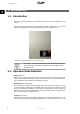
1. Introduction 1 1. Introduction 1.1. Introduction This manual provides information on functionality and maintenance of the TripleLynx CN solar inverter. The inverter display and Web Server are available in Chinese language only. In the manual, English texts appearing in the screenshots and menus are shown for guidance only. Illustration 1.1: TripleLynx CN 8 kW, 10 kW, 12.
1. Introduction power is available (no power is supplied to the grid for 10 minutes). It then goes into connecting mode or off grid mode. 1 Fail Safe (Red LED flashing) If the inverter detects an error in its circuits during the self-test (in connecting mode) or during operation, the inverter goes into fail safe mode. The inverter will remain in fail safe mode until PV power has been absent for a minimum of 10 minutes, or the inverter has been shut down completely (AC + PV).
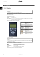
2. Display 2. Display 2 2.1. Display Note: The display activates up to 10 seconds after power up. The integrated display on the inverter front gives the user access to information about the PV system and the inverter. The display has two modes: Normal Power saving The display is in use After 10 min. of no display activity the back light of the display turns off to save power. Re-activate the display by pressing any key Overview of display buttons and functionality: F1 F2 F3 F4 * When an F-key is up.
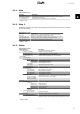
2. Display 2.1.1. View Menu Structure - View Parameter Mode: On grid Prod. today: 12345 kWh Output Power: 12345 W [ --- utilization bar --- ] Description Displays present inverter mode. See operation mode definitions Energy production today in kWh. Value from inverter or S0 energy-meter Current output power in Watt Shows level of inverter utilisation as % of max. utilisation 2 Table 2.1: View 2.1.2.
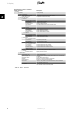
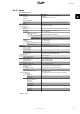
2. Display Menu Structure - Status - Continued Display Functions [-] Inverter [-] Country: [-] Internal Conditions Power module 1: 100 oC PCB1 (AUX): 100 oC [-] Serial no. and SW ver. [-] Inverter Prod- and serial number: A0010000201 011900H2304 Software version: MAC address: ...
2. Display 2.1.4.
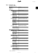
2. Display Menu Structure - Production Log - Continued Display Functions Description [-] Time stamps Installed: 31-12-07 Date of first grid connection Power down: 21:00:00 When the inverter was last connected to grid Prod. initiated: 06:00:00 When the inverter first connected to grid today [-] De-rating Total de-rate: 0 h Period of time the inverter has limited power production in total, shown in hours. Freq. stabiliza.
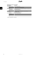
2. Display 2.1.5. Setup Menu Structure - Setup Display Functions [-] External Alarm Stop Alarm Description Only applicable if external alarm is connected Stop alarm Includes testing red LED on front Test Alarm Alarm state: Disabled Alarm time-out: [-] Setup details 009 s alarm time limit.
2. Display Menu Structure - Setup - Continued Display Functions GPRS connection setup SIM PIN code: 0000 Access point name: name User name: user Password: password Roaming: Disabled [-] Data warehouse service Upload channel: LAN Upload time (h:m): 14:55 Start log upload D.W FTP server address: www.meteocontrol.de D.W server port: 65535 FTP mode: Active D.W. server user name: User D.
3. Web Server Quick Guide 3. Web Server Quick Guide 3.1. Introduction 3 These instructions describe the TLX CN Pro Web Server, which facilitates remote access to the inverter. The Web Server is available in TLX CN Pro and TLX CN Pro+ inverters only. Refer to the download area at www.danfoss.com/solar for the newest instructions. 3.2. Supported Characters For all language versions, the Web Server software supports characters compatible with Unicode.
3. Web Server Quick Guide 3 Illustration 3.1: Product Label 7. At initial startup of the inverter, the inverter runs a setup wizard. 3.3.2. Setup Wizard Step 1 of 7: Master setting To set up a master inverter, click on [Set this inverter as master]. • A scan runs to identify inverters in the network. • A pop-up window shows the inverters successfully identified. Click [OK] to confirm that the correct number of inverters has been found. Illustration 3.
3. Web Server Quick Guide 3 Illustration 3.3: Step 2 of 7: Display Language To change the language setting later, refer to Setup, Setup Details. Step 3 of 7: Time and date Enter • time in 24-hour format • date • time zone Accuracy is important, because date and time are used for logging purposes. Adjustment for daylight savings is automatic. Illustration 3.4: Step 3 of 7: Time and Date To change these settings later, refer to Setup, Inverter details, Set Date and Time.
3. Web Server Quick Guide 3 Illustration 3.5: Step 4 of 7: Installed Power To change the installed power, refer to Setup, Calibration, PV Array. Step 5 of 7: Grid code Select the grid code to match the location of the installation. To meet medium-voltage grid requirements select a grid code ending in MV. • The default setting is [undefined]. Select the grid code again, to confirm. • The setting is activated immediately. Correct selection is essential to comply with local and national standards.
3. Web Server Quick Guide Note: If the initial and confirmation settings are different, • grid code selection is cancelled • the wizard recommences step 5 If initial and confirmation settings match, but are incorrect, contact service.
3. Web Server Quick Guide 3 Illustration 3.8: Step 7 of 7: Inverter startup To change the setup later, access the inverter via the integrated web interface or the display, at inverter level. • To change the name of the inverter, go to [Setup → Inverter details] • To enable master mode, go to [Setup → Inverter details] 3.4. Operation 3.4.1. Web Server Structure The Web Server overview is structured as follows. Illustration 3.9: Overview 1.
3. Web Server Quick Guide 2. 3. • Click on the plant name to display the plant view. • Change the plant name at [Setup → Plant details]. Group menu: Displays groups of inverters: • Inverters join group 1 by default • Click on a group name to display the group view, and a list of inverters in the group. • Change the group name via [Setup → Inverter details] in the inverter view. 3 Group members: Displays the inverter names in the group currently selected.
3. Web Server Quick Guide 3 Illustration 3.
3. Web Server Quick Guide 3.5.
4. Troubleshooting 4. Troubleshooting 4.1. Troubleshooting Only trained and authorised personnel familiar with electrical systems and safety issues may work on inverters and electrical installations. 4 Should the inverter not supply energy as expected, go through the checklist before calling service. 1. Check that the grid is properly connected to the inverter and that the mains switch is not switched off. 2. Check that there is sufficient solar radiation to generate power. UPV >250 V 3.
5. Maintenance 5. Maintenance 5.1. Maintenance Normally, the inverter needs no maintenance or calibration. Ensure the heatsink at the rear of the inverter is not covered. Clean the contacts of the PV load switch once per year. Perform cleaning by cycling the switch to on and off positions ten times.The PV load switch is located at the base of the inverter. 5 5.1.1. Cleaning the Cabinet Clean the inverter cabinet using pressurised air, a soft cloth or a brush. 5.1.2.
Danfoss Solar Inverters A/S Ulsnaes 1 DK-6300 Graasten Denmark Tel: +45 7488 1300 Fax: +45 7488 1301 E-mail: solar-inverters@danfoss.com www.solar-inverters.danfoss.com Danfoss can accept no responsibility for possible errors in catalogues, brochures and other printed material. Danfoss reserves the right to alter its products without notice.