MAKING MODERN LIVING POSSIBLE TripleLynx CN Installation Manual Three-phase – 10, 12.
Contents Contents 1. Safety and Conformity 2 Important Safety Information 2 Hazards of PV Systems 3 PV Load Switch 3 Conformity 4 2. Introduction 5 Introduction 5 Installation Sequence 6 Overview of Inverter 7 3. Installation 8 Installation Dimensions and Patterns 8 Mounting the Inverter 10 Removing the Inverter 12 Opening and Closing the Inverter 12 AC Grid Connection 14 PV Connection 16 Auxiliary Input/Output 17 4.
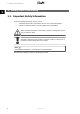
1. Safety and Conformity 1 1. Safety and Conformity 1.1. Important Safety Information All persons installing and servicing inverters must be: • Trained and experienced in general safety rules for work on electrical equipment • Familiar with local requirements, rules and regulations for the installation Safety information important for human safety. Violation of warnings may result in injury to persons or death. Information important for the protection of property.
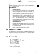
1. Safety and Conformity Before installation: Check for damage to inverter and packaging. If in doubt, contact the supplier before installing the inverter. Installation: For optimum safety, follow the steps described in this manual. Keep in mind that the inverter has two voltage carrying sides; the PV input and the AC grid. Disconnecting the inverter: Before starting work on the inverter, switch off AC grid at the mains switch and PV using the PV load switch.
1. Safety and Conformity 1 1.4. Conformity For approvals and certification information, go to the download area at • www.danfoss.com/solar, Approvals and Certifications • www.danfoss.cn/solar CGC marking - This certifies the conformity of the equipment with the regulations which apply in accordance with China General Certification Center, CGC/GF004:2011.
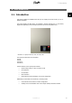
2. Introduction 2. Introduction 2 2.1. Introduction This manual explains the installation and setup of the TripleLynx CN solar inverter, for the installation technician. The inverter display and Web Server are available in Chinese language only. In the manual, English texts appearing in the screenshots and menus are shown for guidance only. Illustration 2.1: TripleLynx CN 8 kW, 10 kW, 12.
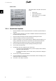
2. Introduction Product Label The product label on the side of the inverter shows: 2 • Inverter type • Important specifications • Serial number, see (1), for identification by Danfoss Illustration 2.2: Product Label 2.1.1. Installation Sequence 6 1. Read the installation manual. Pay special attention to the section Important Safety Information. 2. Install the inverter according to the section Installation Dimensions and Patterns and the section Mounting the Inverter. 3.
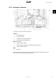
2. Introduction 2.1.2. Overview of Inverter 2 Illustration 2.3: Overview of Danfoss TLX CN inverter Live Part 1. AC Connection Area 2. DC Connection Area 3. Terminal block for parallel connection 4. Auxiliary output: Potential free relay PELV (Safe to touch) 5. Auxiliary interface: RS485 6. Auxiliary interface: Temperature, Irradiation, Energy meter (SO) 7. Auxiliary interface: Ethernet Other 8. DC-switch The TLX CN Pro and TLX CN Pro+ variants can also be configured via the Web Server.
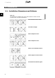
3. Installation 3. Installation 3.1. Installation Dimensions and Patterns 3 Note: When choosing the installation place, ensure that all labels are visible at all times. For details refer to the section Specifications. Avoid constant stream of water. Avoid direct sunlight. Ensure adequate air flow. Ensure adequate air flow. Mount on non-flammable surface. Mount upright on vertical surface. Prevent dust and ammonia gases.
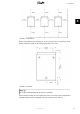
3. Installation 3 Illustration 3.1: Safe Distances Observe these distances when installing one or more inverters. One row mounting is recommended. Contact the supplier for information on mounting in more rows. Illustration 3.2: Wall Plate Note: Use of the wall plate delivered with the inverter is mandatory. Use screws that can safely carry the weight of the inverter. The inverter must be aligned and it is important that the inverter is accessible at the front to allow room for servicing.
3. Installation 3.2. Mounting the Inverter For safe handling of the inverter, two people must carry the unit, or a suitable transport trolley must be used. Safety boots must be worn. 3 Tilt the inverter as shown in the illustration and place the top of the inverter against the mounting bracket. Use the two guides (1) at the top plate to control the inverter horizontally. Illustration 3.
3. Installation Place the lower part of the inverter against the mounting bracket. 3 Illustration 3.5: Place Inverter in Mounting Bracket Lower (4) the inverter and make sure that the hook of the inverter base plate is placed in the lower part of the mounting bracket (5). Check that it is not possible to lift the bottom of the inverter away from the mounting bracket. (6) Fasten the screws on either side of the wall plate to secure the inverter. Illustration 3.
3. Installation 3.3. Removing the Inverter Loosen the locking screws on either side of the inverter. Removal is performed in the reverse order of mounting. With a firm grip at the lower end of the inverter, lift the inverter approximately 20 mm vertically. Pull the inverter slightly away from the wall. Push upwards at an angle until the wall plate releases the inverter. Lift the inverter away from the wall plate. 3 3.4. Opening and Closing the Inverter Remember to observe all ESD safety regulations.
3. Installation Push the front cover upwards. When a slight resistance is felt, give the front cover a tap on the bottom to snap it into holding position. It is recommended to use the holding position instead of dismounting the front cover completely. 3 Illustration 3.8: Open the Inverter To close the inverter, hold on to the lower end of the front cover with one hand and give it a tap on the top until it falls into place. Guide the front cover into place and fasten the two front screws.
3. Installation 3 Illustration 3.10: Fasten Front Screws and Ensure Proper PE Connection The two front screws are the PE connection to the front cover. Make sure that both screws are mounted and fastened with the specified torque. 3.5. AC Grid Connection Note: When choosing the installation place, ensure that all labels are visible at all times. For details refer to the section Specifications.
3. Installation 3 Illustration 3.11: AC Cable Wire Strip Legend 1 Blue cable - Neutral 2 Yellow/green cable - Earth The illustration shows the stripping of insulation of all 5 wires of the AC cable. The length of the PE wire must be longer than the mains and neutral wires. Illustration 3.12: AC Connection Area 1. Verify the inverter matches the grid-voltage. 2. Release main circuit breaker and make precautions to prevent reconnection. 3. Open the front cover. 4.
3. Installation 8. Close the front cover, and remember to verify that both front screws are applied with the correct torque to obtain PE connection. 9. Close main circuit breaker. For safety, check all wiring. Connecting a phase wire to the neutral terminal may permanently damage the inverter. Do not remove the short circuit bridge at (1). 3 3.6. PV Connection Note: When choosing the installation place, ensure that all labels are visible at all times. For details refer to the section Specifications.
3. Installation When unmated the MC4 connectors are not IP54. The intrusion of moisture may occur in the following situations: 1. The inverter runs in Master/Slave operation and only one or two PV inputs are in use. In this case, the other inputs are not connected to PV and they are therefore open to intrusion. 2. Not all PV inputs are connected. 3. PV connectors are not fitted; for example in case of disconnection of parts of a PV plant over a longer period of time.
4. Start-up and Check of Settings 4. Start-up and Check of Settings 4.1. Start-up and Check of Settings Note: Due to the advanced functionalities of the inverter, it may take up to 10 seconds before the display becomes available after power up. 4 Note: For the TLX CN Pro version the first start-up and check of settings can also be performed via the integrated Web Server. For further details, refer to the Web Server User Manual.
4. Start-up and Check of Settings Set time as prompted by the display. Press 'OK' to select number. Press ‘ ▲ ’ to scroll up through the numbers. Select by pressing 'OK'. The clock is 24-hour format. 4 Illustration 4.2: Set Time Note: It is very important to set the time and date accurately as the inverter uses this for logging. If a wrong time/date is accidentally set, correct it immediately in the set date and time menu [Setup → Inverter details → Set date and time].
4. Start-up and Check of Settings Enter the amount of installed PV power for each of the PV inputs. When two or more PV inputs are connected in parallel, each PV input in the parallel group must be set to the total amount of PV power installed to that group divided by the number of parallel inputs. See the table below for examples of installed PV power. 4 Illustration 4.4: Installed PV Power The display will now show “Select grid”. The grid code is set to “undefined” at initial startup.
4. Start-up and Check of Settings Note: If the two grid code selections do not match they will be cancelled and it will be necessary to redo the selections. If an incorrect grid code is accidentally accepted at the first selection, simply accept the “Grid: Undefined” in the confirm grid code screen. This will cancel the country selection and a new selection is possible. If an incorrect grid code is selected twice, call service.
4. Start-up and Check of Settings To enable Master mode go to the Inverter details menu [Setup → Inverter details → Master mode] and set Master mode to Enabled. Ensure that no other master inverters are present in the network prior to carrying out this action. When Master mode is enabled, it is possible to initiate a network scan [Setup → Inverter details → Master mode → Network]. This will show all inverters connected to the master inverter. 4 Illustration 4.
5. Technical Data 5. Technical Data 5.1. Technical Data Nomenclature 1) Pac,r Vac,r Iacmax cosphiac,r fr Vdc,r Vmppmin Vmppmax Vdcmax Vdcstart Vdcmin Idcmax Parameter AC Nom. power AC Reactive power range AC voltage range (P-N) Nominal current AC Max. current AC AC current distortion (THD %) Power factor at 100 % load Controlled power factor range “Connecting” power loss Night-time power loss (off grid) Grid frequency DC Nominal power DC Max.
5. Technical Data 1) 2) 3) 4) 5) According to FprEN 50524. For fixed systems with semi-optimal conditions. At identical input voltages. At unequal input voltages, Vmppmin can be as low as 250 V depending on total input power. SPL (Sound Pressure Level) at 1.5m. Grid Management Box (TLX CN Pro and TLX CN Pro+) or third-party product. 5.2. Norms and Standards Refer to Chapter 1, section Conformity for details. 5.3.
5. Technical Data 5.4. Cable Requirements Cable AC Outer diameter Insulation strip Max. recommended cable length TripleLynx CN 8 kW and 10 kW Max. recommended cable length TripleLynx CN 12.5 kW Condition 5 wire cable All 5 wires 2.5 mm2 4 mm2 6 mm2 10 mm2 4 mm2 6 mm2 10 mm2 6 mm2 10 mm2 Specification Copper 18-25 mm 16 mm 21 m 34 m 52 m 87 m 28 m 41 m 69 m 34 m 59 m Max. recommended cable length TripleLynx CN 15 kW PE Cable diameter at least as phase cables DC Max.
5. Technical Data 5 Illustration 5.2: TripleLynx CN 10 kW Cable Losses [%] versus Cable Length [m] Illustration 5.3: TripleLynx CN 12.5 kW Cable Losses [%] versus Cable Length [m] Illustration 5.4: TripleLynx CN 15 kW Cable Losses [%] versus Cable Length [m] Consider also the following when choosing cable type and cross-sectional area: 26 - Ambient temperature - Layout type (inside wall, under ground, free air etc.
5. Technical Data 5.5. Torque Specifications for Installation 5 Illustration 5.5: Overview of Inverter with Torque Indications, 1-3 Illustration 5.6: Overview of Inverter with Torque Indications, 4-7 1 2 3 4 5 6 7 Parameter Terminal blocks (large) Terminal blocks (small) PE M16 M25 Front screw Locking screw Screwdriver Straight slot 1.0 x 5.5 mm Straight slot 1.0 x 5.5 mm Straight slot 1.0 x 5.5 mm SW 19 mm SW 30 mm TX 30 TX 30 Tightening Torque Min. 1.2 Nm 0.5 Nm 2.
5. Technical Data 5.6. Auxiliary Interface Specifications Parameter Serial Communication Common cable specification RJ45 (2 pcs.) connectors Terminal block Parameter Details Cable jacket diameter (⌀) Cable type Cable Characteristic Impedance Max. cable length Wire gauge Cable shield termination Maximum wire gauge Cable shield termination Max.
5. Technical Data 1) Max. number of inverters are 100. If GSM modem is used for portal upload, the amount of inverters in a network is limited to 50. 2) For outdoor use, we recommend outdoor burial type cable (if buried in the ground) for both Ethernet and RS485. 3) Third input is used for compensation of the irradiation sensor. 4) The number of inverters to be connected in the RS485 network depend on which peripheral device is connected.
5. Technical Data RS485 Terminate the RS485 communication bus at both ends. To terminate the RS485 bus: • Connect Bias L to RX/TX B • Connect Bias H to RX/TX A The RS485 address of the inverter is unique, and defined at the factory. 5 Illustration 5.8: RS485 Communication Detail - Cat 5 T-568A Pinout RS485 1. GND 2. GND 3. RX/TX A (-) 4. BIAS L 5. BIAS H 6. RX/TX B (+) 7. Not connected 8.
5. Technical Data 5.6.1. Network Topology The inverter has two Ethernet RJ45 connectors enabling the connection of several inverters in a line topology as an alternative to the typical star topology. The two ports are similar and may be used interchangeably. For RS485, only linear daisy chain connections can be used. Note: Ring topology is not allowed. 5 Illustration 5.
Danfoss Solar Inverters A/S Ulsnaes 1 DK-6300 Graasten Denmark Tel: +45 7488 1300 Fax: +45 7488 1301 E-mail: solar-inverters@danfoss.com www.solar-inverters.danfoss.com Danfoss (Shanghai) Automatic Controls Co., Ltd. 20th, Floor, Block C, Hi-Tech Building 900 Yi Shan Road Shanghai 200233, P.R.China Tel: +86 (21) 61513000 Fax: +86 (21) 61513100 www.danfoss.com.cn 丹佛斯(上海)自动控制有限公司 上海市宜山路900号科技大楼C楼20层 电话:+86 (21) 61513000 传真:+86 (21) 61513100 www.danfoss.com.cn Rev. date 2011-11-16 Lit. No.