g Installation manual 1000/500/200 Installation 1of 268
Contents Contents 2 of 268 1 1.1 1.2 1.3 Safety information ............................................................................................................. 6 Target group for this manual ............................................................................................... 6 Classes of risk ..................................................................................................................... 6 Electric current ........................................................
Contents Solar-Log 1000/500/200 4.33 4.34 4.35 4.36 4.37 4.38 4.39 4.40 4.41 4.42 4.43 4.44 4.45 4.46 4.47 4.48 4.49 4.50 4.51 4.52 4.53 4.54 4.55 4.56 4.57 4.58 4.59 4.60 4.61 4.62 4.63 4.64 4.65 Evoco ................................................................................................................................. 79 Powercom .......................................................................................................................... 80 SALICRU EQX .........................
Contents 4 of 268 8 8.1 8.2 8.3 8.4 8.5 8.6 8.7 8.8 8.9 8.10 8.11 8.12 8.13 8.14 8.15 8.16 8.17 8.18 8.19 Configuration at a PC .................................................................................................... 148 Starting configuration ...................................................................................................... 148 Overview of “Configuration” menu navigation..................................................................
Contents 10 10.1 10.1.1 10.1.2 10.2 10.3 10.3.1 10.3.2 10.3.3 10.4 10.5 10.5.1 10.5.2 10.5.3 10.5.4 10.6 10.7 10.8 10.9 10.10 10.11 10.12 10.13 10.14 10.15 1000 10.17 10.18 10.19 10.20 10.21 10.22 Solar-Log : Configuration at the unit ....................................................................... 204 Working with the touchscreen .......................................................................................... 204 Main menu – Configuration menu ..........................................
Safety information Target group for this manual 1 Safety information In order to protect people, the product itself, and other equipment, please pay attention to the following before handling the product: the content of this manual particularly the safety information the warning signs and type plates attached to the product 1.
Safety information Electric current 1.3 Electric current DANGER Risk of death by electric shock if inverters are opened. Never open the inverter housing when the inverter is live. Switch inverters off; Page 17 Always read the installation and safety instructions given in the manual for the corresponding inverter.
Assembly instructions Package contents 2 Assembly instructions 2.1 Package contents Check the package contents before proceeding to assembly and installation. Report any damage or missing parts to the forwarding agent immediately.
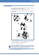
Assembly instructions Wall mounting 2.2 Wall mounting The unit is produced to protection class IP20 and is intended only for installation in interior areas that are dry and dust-free. Suitable wall plugs and screws are supplied for wall mounting. Please remember that there must be a plug and a mains socket available near the Solar-Log™. 1 2 3 5 4 6 Figure 1: Solar-Log™ wall mounting 1 Put the housing where it is to be fitted and mark the drill holes.
Assembly instructions Wall mounting 4 Using a file or a saw, clear the cable feed holes – on top and/or bottom cover – by sawing or filing along the grooves. (Top and bottom covers are identical.
Unit connections Solar-Log200, 500 3 Unit connections 3.1 Solar-Log200, 500 Bottom connections Figure 2: Connections to the bottom side of Solar-Log200, 500 Marking Function RS485/422 B RS485 interface, 6-pin: Connection to inverter, SensorBox or Connection to large display 500 (Solar-Log ). Assignment Page 14. Power 12 V 12 Volt DC voltage input (24 V DC max.
Unit connections Solar-Log1000 3.2 Solar-Log1000 Bottom connections Figure 4: Connections to the bottom side of Solar-Log1000 Marking Function Rel. Relay, for connecting external signals (max. 24 V), 3 pin, e.g. to connect rotating beacons etc. RS485 A RS485 interface, 4-pin: Connection to an inverter, SensorBox or large display (inactive if the optional Bluetooth interface is used) RS485/422 B RS485 interface, 6-pin: Connection to inverter, SensorBox or connection to large display.
Unit connections Solar-Log1000 Insertion slot for SIM card and antenna connection (Solar-Log1000 GPRS) 1000 1000 In addition to the connections on the Standard Solar-Log , the Solar-Log GPRS model with integrated GPRS modem has an insertion slot for the SIM card and a screw connection for a mobile communications antenna.
Unit connections RS485/422 B connection assignments (6-pin) 3.
Unit connections Connection accessories 3.
Connecting the inverters Connection accessories 4 Connecting the inverters As each inverter manufacture uses different wiring connections and connectors, the corresponding data cables must be adapted correctly: You will find the terminal strip block wiring diagram to connect the inverters in table form in the following sections on connecting inverters. For assignment of the RS485/422 B connection to the Solar-Log™, see page 14.
Connecting the inverters De-energise the inverter and Solar-Log™ 4.1 De-energise the inverter and Solar-Log™ De-energising the inverter Before a making a cable connection between the Solar-Log™ and the connections inside the inverter and before installing an interface card in the inverter, always turn all inverters off.
Connecting the inverters SMA 4.2 SMA 4.2.1 Overview SMA inverters do not have an integrated RS485 interface. However, the following RS485 interfaces can be retrofitted to SMA inverters: Special RS485 piggyback card (by Solare Datensysteme GmbH) Original SMA RS485 piggyback card (by SMA) Both piggyback cards can be installed in “Sunny Boy” inverters (except for 3000/4000/5000TL-20 next generation models) or “Sunny Mini Central” by SMA.
Connecting the inverters SMA 4.2.2 SMA connection using special RS485 piggyback card Overview Interface not integrated. retrofit the special RS485 piggyback card Where to connect: Terminal strip inside the inverter on the piggyback Communication address does not have to be allocated.
Connecting the inverters SMA Connect inverters to the Solar-Log™ The wiring is done using the – ready-made data cable (optional extra; not supplied) or – self-made, shielded 4 wire data cable and terminal block connector ( Page 15). Procedure 1 Pull the free wires through the wire opening in the inverter.
Connecting the inverters SMA Connecting the inverters to each other (Solar-Log500, Solar-Log1000) Connect using a 4 wire, shielded data cable (e.g. a 25 m ring cable, Solare Datensysteme order no. 220014) Where to connect: Terminal block in inverter (on the retrofitted RS485 interface) Procedure 1 Pull the wire in the inverter through the insulation tube that is attached to the piggy back. The wire must be encased in the insulation tube inside all inverters.
Connecting the inverters SMA 4.2.3 Connect SMA with original SMA RS485 piggy back and the SMA RS485 data module Overview Interface not integrated. Retrofit SMA RS485 piggy back Where to connect: Terminal strip inside the inverter on the piggyback Communication address does not have to be allocated.
Connecting the inverters SMA 5 Connect the earth: Connect terminal 5 of the inverter to the inverter housing using the supplied flatstrip connector. 6 If only one inverter is to be connected it must be terminated. Attach the supplied jumper to the bottom pins on the connector strip: 7 Close the inverter if no other inverters are to be connected. 8 Insert the terminal block connector into the Solar-Log™ RS485 socket.
Connecting the inverters SMA 4.2.4 SMA Bluetooth mode Bluetooth mode is only possible if the optional Bluetooth module is installed in the Solar-Log™. ™ Bluetooth mode is possible only with Solar-Log BT models. All SMA Bluetooth inverters are supported, even Bluetooth piggyback cards. Overview No preparation of the inverters is required. All SMA Bluetooth piggy backs supported Simultaneous operation with SMA SunnyBeam Bluetooth is not possible.
Connecting the inverters Kaco – Powador 4.3 Kaco – Powador Overview Interface integrated Where to connect: Terminal strip inside the inverter 2 pin wiring Communication address must be allocated. Work steps • • • • Switch off the inverters and SolarLog™; Page 17 Connect inverters to the Solar-Log™ Connect the inverters to each other Allocate communication address Note Wiring instructions and diagram forInterconnection of Kaco Powador inverters can be found in the Appendix; Page 264.
Connecting the inverters Kaco – Powador Connecting the inverters to each other (Solar-Log500, Solar-Log1000) Connect using a 2 wire, shielded data cable. Where to connect: Terminal strip inside the inverter The RS485 connections on the terminal strip are each double connections so that the wiring can be continued to the next inverter. Procedure 1 Connect the data cable to the free terminals A and B of inverter 1. 2 Insert the other end of the cable into terminals A and B of inverter 2.
Connecting the inverters Kaco – PVI-BluePlanet 4.4 Kaco – PVI-BluePlanet Overview The Solar-Log™ only works with Kaco BluePlanet inverters that have an RS485 interface. The RS232-interface is not supported. RS232 models: RS485 models: RS485 interface can be retrofitted by the manufacturer. Interface integrated Where to connect: Terminal strip inside the inverter 2 pin wiring Communication address must be allocated.
Connecting the inverters SolarMax – S and C series Connecting the inverters to each other (Solar-Log500, Solar-Log1000) Connect using a 2 wire, shielded data cable. Where to connect: Terminal strip inside the inverter The RS485 connections on the terminal strip are each double connections so that the wiring can be continued to the next inverter. Procedure 1 Open the inverter as described in the inverter instructions. 2 Connect the data cable to the free terminals A and B of inverter 1.
Connecting the inverters SolarMax – S and C series Connecting inverters to the Solar-Log™ The wiring is done using the ready-made data cable (optional extra; not supplied) or your own fabricated RS485 data cable with RJ45 plug and terminal block connector ( Page 15) CAUTION Risk of damage to the unit! The Solar-Log™ also has an RJ45 socket, which must never be connected to the RJ45 socket on the inverter.
Connecting the inverters SolarMax – Cx series Procedure 1 Insert the RJ45 plug into the free RJ45 socket on inverter 1. 2 Insert the other end of the wire into any RJ45 socket on inverter 2. 3 Connect the other inverters to each other in the same way. 4 Terminate on the last inverter: Insert the connection plug into the free RJ45 socket. Allocating communication address Recommendation: Continuous numbering starting with 1.
Connecting the inverters SolarMax – Cx series Connecting inverters to the Solar-Log™ The wiring is done using the ready-made data cable (optional extra; not supplied) or your own fabricated RS485 data cable with RJ45 plug and terminal block connector ( Page 15) CAUTION Risk of damage to the unit! The Solar-Log™ also has an RJ45 socket, which must never be connected to the RJ45 socket on the inverter.
Connecting the inverters SolarMax – E series Connecting the inverters to each other (Solar-Log500, Solar-Log1000) Connect using a network cable (patch cable) Where to connect: RJ45 socket inside the inverter (on the retrofitted RS485 interface) Procedure 1 Open the inverter as described in the inverter instructions. 2 Insert the RJ45 plug into any RJ45 socket on inverter 1. 3 Insert the other end of the wire into any RJ45 socket on inverter 2.
Connecting the inverters SolarMax – E series Connecting inverters to the Solar-Log™ The wiring is done using the ready-made data cable (optional extra; not supplied) or your own fabricated cable connection with RS485 data cable, RJ45 plug and terminal block connector ( Page 15) CAUTION Risk of damage to the unit! The Solar-Log™ also has an RJ45 socket, which must never be connected to the RJ45 socket on the inverter.
Connecting the inverters Fronius with ComCard Connecting the inverters to each other (Solar-Log500, Solar-Log1000) Connect using the RS485 data cable with an RJ45 plug Where to connect: RJ45 socket inside the inverter (on the retrofitted RS485 interface) Procedure 1 Open the inverter as described in the inverter instructions. 2 Run the wire from inverter 1 to inverter 2 through the hole for the wire on the bottom of the unit. 3 Insert the RJ45 plug into the “RS485 in” socket in inverter 1.
Connecting the inverters Fronius with ComCard Installing Fronius ComCard RS485 interface Procedure Install the Fronius ComCard RS485 interface in the inverter in accordance with the interface card installation instructions.
Connecting the inverters Danfoss Connecting the inverters to each other (Solar-Log500, Solar-Log1000) Connect using a network cable (patch cable) Where to connect: RJ45 socket on the outside of the inverter Procedure 1 Insert the RJ45 plug in inverter 1 into the OUT socket. 2 Insert the other end of the wire into the IN socket on inverter 2. 3 Connect the other inverters to each other in the same way. 4 Terminate in the last inverter: Insert the supplied connection plug into the RJ45 OUT socket.
Connecting the inverters Danfoss Procedure 1 Unscrew the side cover as shown in the inverter's instructions. 2 If you are fabricating the cable yourself, connect the wires as shown in the following diagram: Solar-Log™ terminal block connector RJ45 inverter Terminal Pin 1 6 3 1 3 2 4 3 CAUTION Risk of damage to the unit! The Solar-Log™ also has an RJ45 socket, which must never be connected to the RJ45 socket on the inverter.
Connecting the inverters Mitsubishi with RS485 interface 4.10 Mitsubishi with RS485 interface Overview Interface integrated Where to connect: 2 RJ11 sockets inside the inverter. 2 pin wiring Communication address must be allocated.
Connecting the inverters Power-One/Aurora Connecting the inverters to each other (Solar-Log500, Solar-Log1000) Connect using a data cable with an RJ11 plug Where to connect: 2 RJ11 sockets on the bottom left inside the inverter. Procedure 1 Unscrew the front plate of the inverter as shown in the inverter's instructions. 2 Insert the RJ11 plug into any RJ11 socket on inverter 1. 3 Insert the other end of the wire into any RJ11 socket on inverter 2.
Connecting the inverters Power-One/Aurora Procedure 1 Open the inverter as described in the inverter instructions. 2 Pull the free wires through the wire opening in the inverter.
Connecting the inverters Sunways – AT/NT 4.12 Sunways – AT/NT Overview Interface integrated Where to connect: Terminal strip inside the inverter – 750 V models: 4 RS485 terminals on 10 pin terminal strip – 850 V models: 4 pin RS485 terminal strip 2 pin wiring Communication address must be allocated.
Connecting the inverters Vaillant – auroPOWER VPI /1 and VPI (RS485) Connecting the inverters to each other (Solar-Log500, Solar-Log1000) Connect using a 2 wire, shielded data cable. Where to connect: Terminal strip inside the inverter – 750 V models: 4 RS485 terminals on 10 pin terminal strip – 850 V models: 4 pin RS485 terminal strip The RS485 connections on the terminal strip are each double connections so that the wiring can be continued to the next inverter.
Connecting the inverters Vaillant – auroPOWER VPI /1 and VPI (RS485) Connecting inverters to the Solar-Log™ The wiring is done using the ready-made data cable (optional extra; not supplied) or self-made, shielded 2 wire data cable and terminal block connector ( Page 15). Procedure 1 Open the inverter as described in the inverter instructions. 2 Pull the free wires through the wire opening in the inverter.
Connecting the inverters Solutronic SP25-55 (RS485) Allocating communication address Recommendation: Continuous numbering starting with 1. Setting: Units without transformers: using the DIP switch inside the inverter Units with transformers: using the inverter operating display. Procedure: As set out in the inverter's instructions 4.
Connecting the inverters Solutronic SP25-55 (RS485) Procedure 1 If you are fabricating the cable yourself, connect the wires as shown in the following diagram: Solar-Log™ terminal block connector Inverter terminal strip Terminal Terminal 1 Pin 1 RS485-A 3 Pin 3 GND 4 Pin 2 RS485 B 2 If only one inverter is to be connected it must be terminated. You will find detailed instructions for setting the inverters on the Solutronic website.
Connecting the inverters Solutronic SP100, SP120 (RS485) 4.15 Solutronic SP100, SP120 (RS485) Overview Interface integrated Where to connect: Round pin plug on the outside of the inverter. 3 pin wiring Communication address must be allocated. All inverters must be fitted with firmware version 1.2.39 or later. Inverters must be earthed otherwise this could lead to problems with inverter detection.
Connecting the inverters Schüco SGI series (RS485) Procedure 1 Insert the plug into the X6 socket on inverter 1. 2 Insert the other end of the wire into the X7 socket on inverter 2. 3 Connect the other inverters to each other in the same way. 4 Terminate in the last inverter in accordance with the manufacturer's handbook. Allocating communication address Setting: Via the inverter's operating display in the Communication menu; parameter 89 Recommendation: Consecutive numbering starting with 1.
Connecting the inverters Schüco SGI series (RS485) Procedure 1 If you are fabricating the cable yourself, connect the wires as shown in the following diagram: Solar-Log™ terminal block connector RJ45 inverter Terminal Pin 4 3 (A) 1 6 (B) 2 Open the unit cover on the bottom of the inverter. 3 Insert the RJ45 plug into the RJ45 socket on the inverter.
Connecting the inverters REFUSOL 4.17 REFUSOL Overview Interface integrated Where to connect: RS485 socket on the bottom of the inverter 2 pin wiring Communication address must be allocated.
Connecting the inverters REFUSOL Connecting the inverters to each other (Solar-Log500, Solar-Log1000) Connect using – a 2 wire shielded data cable and – 4 pin “SACC-M12MS-4SC” plugs (2 supplied with the inverter). Where to connect: RS485 sockets on the bottom of the inverter. The RS485 IN and OUT sockets are each double connections so that the wiring can be continued to the next inverter. Procedure 1 Connect the data cable to the “SACC-M12MS-4SC” plug as shown in the inverter's instructions.
Connecting the inverters REFUSOL Older Solar-Log™/Refusol installations: Set compatibility With earlier Solar-Log™/Refusol installations the inverter had to be set with additional parameters for Solar-Log™ compatibility. This is only still necessary if an inverter has been replaced because it was faulty or if the system is extended. In these cases the new inverters must also be provided with the advanced parameters again.
Connecting the inverters Kostal Pico and Solar factory Convert T inverter (RS485) 4.18 Kostal Pico and Solar factory Convert T inverter (RS485) Overview Interface integrated Where to connect: Terminal strip inside the inverter 3 pin wiring Communication address must be allocated. Multi-string technology Pico/Convert inverters are fitted with several MPP trackers. Each string input is monitored separately and perfectly adjusted to the connected modules.
Connecting the inverters Kostal Pico and Solar factory Convert T inverter (RS485) Connecting the inverters to each other (Solar-Log500, Solar-Log1000) Connect using a 3 wire, shielded data cable. Where to connect: Terminal strip inside the inverter Procedure 1 Open the inverter as described in the inverter instructions. 2 Connect terminals A, B and GND of inverter 1 to the corresponding terminals on inverter 2. 3 Connect the other inverters to each other in the same way.
Connecting the inverters Mastervolt (RS485) 4.19 Mastervolt (RS485) Overview Interface integrated Where to connect: RJ45 plug outside the housing floor. 2 pin wiring Communication address does not have to be allocated. Multi-string technology Mastervolt inverters are fitted with 1 or 2 MPP trackers depending on the model. Each string input is monitored separately and perfectly adjusted to the connected modules. Some inverters are also divided internally into 2 or even 3 individual inverters.
Connecting the inverters Mastervolt (RS485) Procedure 1 If you are fabricating the cable yourself, connect the wires as shown in the following diagram: Solar-Log™ terminal block connector RJ45 inverter Terminal Pin 1 4 4 3 2 Insert the RJ45 plug into the RJ45 socket on the inverter. 3 If only one inverter is to be connected terminate this in accordance with the inverter instructions. 4 Insert the terminal block connector into the Solar-Log™ RS485 socket.
Connecting the inverters AEG PS (RS485) 4.20 AEG PS (RS485) Overview Interface not integrated. Retrofit RS485 interface card. 4 pin connection – only on RS485/422 B connection of the Solar-Log™ Communication address does not have to be allocated. Multi-string technology AEG inverters are fitted with 1 or 3 MPP trackers depending on the model. Each string input is monitored separately and perfectly adjusted to the connected modules.
Connecting the inverters AEG PS (RS485) Procedure 1 Open the inverter as described in the inverter instructions. 2 Pull the free wires through the wire opening in the inverter.
Connecting the inverters Eaton (RS485) 4.21 Eaton (RS485) Overview Interface not integrated. Retrofit RS485 interface card. 4 pin connection – only on RS485/422 B connection of the Solar-Log™ Communication address does not have to be allocated. Multi-string technology Eaton inverters are fitted with 1 or 3 MPP trackers depending on the model. Each string input is monitored separately and perfectly adjusted to the connected modules.
Connecting the inverters Eaton (RS485) Procedure 1 Open the inverter as described in the inverter instructions. 2 Pull the free wires through the wire opening in the inverter.
Connecting the inverters Suntension (RS485) 4.22 Suntension (RS485) Overview Interface not integrated. Retrofit RS485 interface card. 4 pin connection – only on RS485/422 B connection of the Solar-Log™ Communication address does not have to be allocated. Multi-string technology Suntension inverters are fitted with 1 or 3 MPP trackers depending on the model. Each string input is monitored separately and perfectly adjusted to the connected modules.
Connecting the inverters Suntension (RS485) Procedure 1 Open the inverter as described in the inverter instructions. 2 Pull the free wires through the wire opening in the inverter.
Connecting the inverters Riello (RS485) 4.23 Riello (RS485) Overview Interface not integrated. Retrofit RS485 interface card. 4 pin connection – only on RS485/422 B connection of the Solar-Log™ Communication address does not have to be allocated. Multi-string technology Riello inverters are fitted with 1 or 3 MPP trackers depending on the model. Each string input is monitored separately and perfectly adjusted to the connected modules.
Connecting the inverters Riello (RS485) Procedure 1 Open the inverter as described in the inverter instructions. 2 Pull the free wires through the wire opening in the inverter.
Connecting the inverters Diehl AKO with RS485 interface 4.24 Diehl AKO with RS485 interface Overview Interface integrated Where to connect: RJ45 socket on the bottom of the inverter 2 pin wiring Communication address does not have to be allocated. Note The order in which the inverters are displayed in the Solar-Log™ after detection is random.
Connecting the inverters Ingeteam Connecting the inverters to each other (Solar-Log500, Solar-Log1000) Connect using a network cable (patch cable) Where to connect: RJ45 sockets on the bottom of the inverter Procedure 1 Insert the RJ45 plug into any RJ45 socket on inverter 1. 2 Insert the other end of the wire into any RJ45 socket on inverter 2. 3 Connect the other inverters to each other in the same way. 4 Terminate in the last inverter in accordance with the inverter instructions. 4.
Connecting the inverters Ingeteam Procedure 1 Open the inverter as described in the inverter instructions. 2 Pull the free wires through the wire opening in the inverter.
Connecting the inverters Voltwerk (only for Solar-Log1000) 4.26 Voltwerk (only for Solar-Log1000) Note 1000 Voltwerk inverters can only be connected to the Solar-Log has a CAN interface. , as only this one The following description relates to inverters without transformers produced in or after 2007. Overview Can only be used on the Solar-Log1000 (CAN interface). Interface integrated Where to connect: CAN socket on the outside of the bottom of the inverter. Only use ready-made cable sets.
Connecting the inverters Conergy (only Solar-Log1000) Connecting the inverters to each other (only Solar-Log1000) Connection is made only with a ready-made data cable specially for connecting the inverters to each other (optional extra: not supplied). Where to connect: CAN socket outside the inverter Procedure 1 Insert the CAN plug into any CAN OUT socket on inverter 1. 2 Insert the other end of the wire into any CAN IN socket on inverter 2. 3 Connect the other inverters to each other in the same way.
Connecting the inverters Conergy (only Solar-Log1000) Connecting inverters to the Solar-Log1000 Connection is only done using a ready-made data cable, specially for connect1000 ing to the Solar-Log (optional extra; not supplied). Procedure 1 Insert the CAN plug into the inverter CAN IN socket. 2 If only one inverter is to be connected it must be terminated: Insert the two 5 pin 120 Ω terminal resistors from the ready-made cable set into the CAN OUT socket.
Connecting the inverters Suntechnics (only Solar-Log1000) 4.28 Suntechnics (only Solar-Log1000) Note 1000 Suntechnics inverters can only be connected to the Solar-Log one has a CAN interface. , as only this The following description relates to inverters without transformers produced in or after 2007. Overview Can only be used on Solar-Log1000 (CAN interface). Interface integrated Where to connect: CAN socket on the outside of the bottom of the inverter. Only use ready-made cable sets.
Connecting the inverters Effekta Connecting the inverters to each other (only Solar-Log1000) Connection is made only with a ready-made data cable specially for connecting the inverters to each other (optional extra: not supplied). Where to connect: CAN socket outside the inverter Procedure 1 Insert the CAN plug into any CAN OUT socket on inverter 1. 2 Insert the other end of the wire into any CAN IN socket on inverter 2. 3 Connect the other inverters to each other in the same way.
Connecting the inverters Effekta Procedure 1 Open the inverter as described in the inverter instructions. 2 If you are fabricating the cable yourself, connect the wires as shown in the following diagram: Solar-Log™ terminal block connector Inverter terminal strip Terminal Terminal 1 Pin 2 RS485 A (+) 3 Pin 3 GND 4 Pin 1 RS485 B (-) 3 If only one inverter is to be connected it must be terminated: Set the jumper on the RS485 interface card to ON.
Connecting the inverters ALPHA-SOL 4.30 ALPHA-SOL Overview Interface not integrated. Retrofit RS485 interface card. 4 pin wiring Communication address must be allocated. Work steps • • • • • Allocate communication address Switch off the inverters and the SolarLog™; Page 17 Install the RS485 interface in the inverter Connect inverters to the Solar-Log™ Connect the inverters to each other Allocating communication address Recommendation: Continuous numbering starting with 1.
Connecting the inverters ALPHA-SOL Example - Communication address 4: On Off DIP switch 1 4 5 6 7 8 4 5 6 7 8 2 3 Example - Communication address 5: On Off DIP switch 1 2 3 You will find more information at: http://de.wikipedia.org/wiki/Dualsystem Installing the RS485 interface Procedure Install the RS485 interface in the inverter in accordance with the interface card installation instructions.
Connecting the inverters Europa-Solar AG (RS485) 5 Close the inverter if no other inverters are to be connected. 6 Insert the terminal block connector into the Solar-Log™ RS485 socket. Connecting the inverters to each other (Solar-Log500, Solar-Log1000) Connect using a 4 wire, shielded data cable. Where to connect: Terminal strip inside the inverter on the retrofitted RS485 interface card Procedure 1 Open the inverter as described in the inverter instructions.
Connecting the inverters Europa-Solar AG (RS485) Connecting inverters to the Solar-Log™ The wiring is done using the ready-made BRJ1 data cable (optional extra; not supplied) or your own fabricated cable connection with RJ45 plug and terminal block connector ( Page 15) CAUTION Risk of damage to the unit! The Solar-Log™ also has an RJ45 socket, which must never be connected to the RJ45 socket on the inverter. Only connect inverters via the RS485/422 B Solar-Log™ interface.
Connecting the inverters Ever-Solar (Eversol TL RS485) 4 Connect the other inverters to each other in the same way. 5 Terminate in the last inverter in accordance with the inverter instructions. 6 Close inverters. 4.32 Ever-Solar (Eversol TL RS485) Overview Interface not integrated. Retrofit RS485 interface card. Where to connect: RJ45 socket on the outside of the inverter 4 pin connection – only on RS485/422 B connection of the Solar-Log™ Communication address does not have to be allocated.
Connecting the inverters Ever-Solar (Eversol TL RS485) Procedure CAUTION Risk of damage to the unit! The Solar-Log™ also has an RJ45 socket, which must never be connected to the RJ45 socket on the inverter. Only connect inverters via the RS485/422 B Solar-Log™ interface. 1000 Note concerning Solar-Log : Only connect inverter using the RS485/422 B interface.
Connecting the inverters Evoco 4.33 Evoco Overview Interface integrated Where to connect: Between the COM round sockets on the outside of the inverter. 2 pin wiring Communication address must be allocated.
Connecting the inverters Powercom Procedure 1 Insert the round plug into any round socket on inverter 1. 2 Insert the other end of the wire into any round socket on inverter 2. 3 Connect the other inverters to each other in the same way. 4 Terminate in the last inverter in accordance with the inverter instructions. Allocating communication address Recommendation: Continuous numbering starting with 1. Default settings on the inverter: Communication address 1.
Connecting the inverters Powercom Example - Communication address 2: On Off DIP switch 1 2 3 4 5 6 7 8 3 4 5 6 7 8 4 5 6 7 8 4 5 6 7 8 Example - Communication address 3: On Off DIP switch 1 2 Example - Communication address 4: On Off DIP switch 1 2 3 Example - Communication address 5: On Off DIP switch 1 2 3 You will find more
Connecting the inverters Powercom Procedure 1 Open the inverter as described in the inverter instructions. 2 Pull the free wires through the wire opening in the inverter. 3 If you have made the cable connection yourself connect the wires as shown in the following diagram: Solar-Log™ terminal block connector Inverter terminal strip Terminal Terminal 1 R+ 1 T+ 4 R- 4 T- 4 If only one inverter is to be connected terminate this in accordance with the inverter instructions.
Connecting the inverters SALICRU EQX 4.35 SALICRU EQX Overview Interface not integrated. Retrofit RS485 interface card. 4 pin connection – only on RS485/422 B connection of the Solar-Log™ Communication address does not have to be allocated. Multi-string technology The inverters are fitted with 1 or 3 MPP trackers depending on the model. Each string input is monitored separately and perfectly adjusted to the connected modules.
Connecting the inverters SALICRU EQX Procedure 1 Open the inverter as described in the inverter instructions. 2 Pull the free wires through the wire opening in the inverter.
Connecting the inverters SALICRU EQXLV 4.36 SALICRU EQXLV Overview Interface integrated 2 pin wiring Communication address must be allocated.
Connecting the inverters Santerno Allocating communication address Recommendation: Continuous numbering starting with 1. Setting: Using PC software for configuring inverters Procedure: As set out in the inverter's instructions 4.37 Santerno Overview Interface integrated. Where to connect: 9 pin socket on the outside of the housing floor. 2 pin wiring. Communication address must be allocated.
Connecting the inverters Santerno Connecting the inverters to each other (Solar-Log500, Solar-Log1000) Santerno inverter data cable (optional extra; not supplied) Where to connect: 9 pin socket on the outside of the housing floor. Procedure 1 Insert the Santerno inverter data cable plug into socket B of inverter 1. 2 Insert the Santerno inverter data cable plug into socket C of inverter 1. 3 Insert the plug on the other end of the cable into socket C of inverter 2.
Connecting the inverters Schneider Electric SunEzy 4.38 Schneider Electric SunEzy Overview Interface not integrated. Retrofit RS485 interface card. 4 pin connection – only on RS485/422 B connection of the Solar-Log™ Communication address does not have to be allocated. Multi-string technology The inverters are fitted with 1 or 3 MPP trackers depending on the model. Each string input is monitored separately and perfectly adjusted to the connected modules.
Connecting the inverters Schneider Electric SunEzy Procedure 1 Open the inverter as described in the inverter instructions. 2 Pull the free wires through the wire opening in the inverter.
Connecting the inverters Steca 4.39 Steca Overview Interface integrated Where to connect: RJ45 socket outside on the inverter interface card. 2 pin wiring Communication address must be allocated.
Connecting the inverters WINAICO Connecting the inverters to each other (Solar-Log500, Solar-Log1000) Connect using the RS485 data cable with RJ45 plug; Connection cables between the inverters are supplied with the inverters. Use these. Where to connect: RJ45 socket on the outside of the inverter Procedure 1 Insert the RJ45 plug into the free RJ45 socket on inverter 1. 2 Insert the other end of the wire into any RJ45 socket on inverter 2. 3 Connect the other inverters to each other in the same way.
Connecting the inverters WINAICO Example - Communication address 1: On Off DIP switch 1 2 3 4 5 6 7 8 3 4 5 6 7 8 3 4 5 6 7 8 4 5 6 7 8 4 5 6 7 8 Example - Communication address 2: On Off DIP switch 1 2 Example - Communication address 3: On Off DIP switch 1 2 Example - Communication address 4: On Off DIP switch 1
Connecting the inverters WINAICO Connecting inverters to the Solar-Log™ The wiring is done using the ready-made BKL2 data cable (optional extra; not supplied) or self-made, shielded 4 wire data cable and terminal block connector ( Page 15). Procedure 1 Open the inverter as described in the inverter instructions. 2 Pull the free wires through the wire opening in the inverter.
Connecting the inverters Delta (RS485) 4.41 Delta (RS485) Overview Interface integrated Where to connect: RJ45 socket on the outside of the inverter 2 pin wiring Communication address must be allocated.
Connecting the inverters Sungrow Connecting the inverters to each other (Solar-Log500, Solar-Log1000) Connect using a network cable (patch cable) Where to connect: RJ45 sockets on the outside of the inverter. Procedure 1 Insert the RJ45 plug into any RJ45 socket on inverter 1. 2 Insert the other end of the wire into any RJ45 socket on inverter 2. 3 Connect the other inverters to each other in the same way. 4 Terminate in the last inverter: Insert the 120 Ω resistor into the free RJ45 socket.
Connecting the inverters Sungrow Procedure 1 If you are fabricating the cable yourself, connect the wires as shown in the following diagram: Solar-Log™ terminal block connector Inverter round socket Terminal Pin 1 1 (A) 4 2 (B) 2 Insert round plug into socket B on the inverter. 3 If only one inverter is to be connected terminate this in accordance with the inverter instructions. 4 Insert the terminal block connector into the Solar-Log™ RS485 socket.
Connecting the inverters Sustainable Energy 4.43 Sustainable Energy Overview Interface integrated 2 pin wiring Communication address must be allocated.
Connecting the inverters Motech (RS485) Allocating communication address Recommendation: Continuous numbering starting with 1. Setting: Using PC software for configuring inverters Procedure: As set out in the inverter's instructions 4.44 Motech (RS485) Overview Interface integrated Where to connect: RJ45 plug outside the housing floor 2 pin wiring Communication address does not have to be allocated.
Connecting the inverters Motech (RS485) Procedure 1 If you are fabricating the cable yourself, connect the wires as shown in the following diagram: Solar-Log™ terminal block connector RJ45 inverter Terminal Pin 1 7 4 8 2 Insert the RJ45 plug into the RJ45 socket on the inverter. 3 If only one inverter is to be connected terminate this in accordance with the inverter instructions. 4 Insert the terminal block connector into the Solar-Log™ RS485 socket.
Connecting the inverters Zentral Solar Deutschland (RS485) 4.45 Zentral Solar Deutschland (RS485) Overview Interface integrated Where to connect: RJ45 plug outside the housing floor 2 pin wiring Communication address does not have to be allocated.
Connecting the inverters AROS Solar Technology Connecting the inverters to each other (Solar-Log500, Solar-Log1000) Connect using a network cable (patch cable) Where to connect: RJ45 sockets on the outside of the inverter. Procedure 1 Insert the RJ45 plug into any RJ45 socket on inverter 1. 2 Insert the other end of the wire into any RJ45 socket on inverter 2. 3 Connect the other inverters to each other in the same way. 4 Terminate in the last inverter in accordance with the inverter instructions. 4.
Connecting the inverters AROS Solar Technology Connecting inverters to the Solar-Log™ The wiring is done using the ready-made BRJ1 data cable (optional extra; not supplied) or your own fabricated cable connection with RJ45 plug and terminal block connector ( Page 15) CAUTION Risk of damage to the unit! The Solar-Log™ also has an RJ45 socket, which must never be connected to the RJ45 socket on the inverter. Only connect inverters via the RS485/422 B Solar-Log™ interface.
Connecting the inverters General Electric inverters (GE) 4.47 General Electric inverters (GE) Overview Interface integrated Connected using network cable (patch cable) and Ethernet router or -switch Communication address must be allocated. Work steps • • • Allocate communication address Connect inverters to the Solar-Log™ Connect the inverters to each other Allocating communication address Recommendation: Continuous numbering starting with 1.
Connecting the inverters Hyundai HPC-050HT-E and HPC-100HT-E 4.48 Hyundai HPC-050HT-E and HPC-100HT-E Overview Interface integrated Where to connect: RJ45 CN socket on the outside of the inverter. 2 pin wiring Communication address must be allocated.
Connecting the inverters Hyundai HPC-250HT-E Connecting the inverters to each other (Solar-Log500, Solar-Log1000) Connect using a network cable (patch cable) Where to connect: RJ45 sockets on the outside of the inverter. Procedure 1 Insert the RJ45 plug into any RJ45 socket on inverter 1. 2 Insert the other end of the wire into any RJ45 socket on inverter 2. 3 Connect the other inverters to each other in the same way. 4 Terminate in the last inverter in accordance with the inverter instructions.
Connecting the inverters Hyundai HPC-250HT-E CAUTION Risk of damage to the unit! The Solar-Log™ also has an RJ45 socket, which must never be connected to the RJ45 socket on the inverter. Only connect the inverter using the RS485/422 B interface of the 1000 Solar-Log™ or on the Solar-Log also via the RS485 A interface.
Connecting the inverters EKO Energy 4.50 EKO Energy Overview Interface integrated Where to connect: Between the COM round sockets on the outside of the inverter. 2 pin wiring Communication address must be allocated.
Connecting the inverters Q3 (RS485) Procedure 1 Insert the round plug into any round socket on inverter 1. 2 Insert the other end of the wire into any round socket on inverter 2. 3 Connect the other inverters to each other in the same way. 4 Terminate in the last inverter in accordance with the inverter instructions. Allocating communication address Recommendation: Continuous numbering starting with 1.
Connecting the inverters Siemens Connecting the inverters to each other (Solar-Log500, Solar-Log1000) Connection using your own fabricated daisy chain cable. Where to connect: X2 connection socket on outside of the inverter. Procedure 1 Insert the plug into socket X2 on inverter 1. 2 Insert the other end of the wire into the X2 socket on inverter 2. 3 Connect the other inverters to each other in the same way. 4 Terminate in the last inverter in accordance with the inverter instructions.
Connecting the inverters Siemens Connecting the Solar-Log™ to inverter 1 Solar-Log™ (4/6 pin terminal plug) Inverter 1 - RS485 IN (4 pin round plug) Pin 1 (white) to Pin 2 Pin 4 (brown) to Pin 3 If only one inverter is to be connected this must be terminated (see following item “Bus termination”). Connecting inverters to each other (Solar-Log500, Solar-Log1000) Inverters must be connected to each other using shielded data cables via the RS485 connections located on the SINVERT PVM.
Connecting the inverters Siemens Setting parameters Parameters are set using the display on the inverter. The date and time must be correctly set and the password 72555 entered before the communication settings. The communication parameters are set in the sub-menu “F1 -> Configuration -> Communication -> RS 485”. The individual menu items are selected with the arrow keys ↑↓ and confirmed by pressing ENTER. A consecutive communication address must be allocated to each SINVERT PVM.
Connecting the inverters Albatech APL Triphase 15 / 20 4.53 Albatech APL Triphase 15 / 20 Inverters from different Albatech model ranges (APL monophase/triphase) cannot be mixed on an RS485 connection. The correct range must be selected when selecting inverters. Overview Interface integrated Where to connect: Terminal strip inside the inverter 3 pin wiring Communication address must be allocated.
Connecting the inverters Albatech APL Triphase 15 / 20 4. If your have made the cable yourself, connect the wires as shown in the following diagram: Solar-Log™ terminal block connector Inverter terminal strip Terminal Pin 1 (Data +) 15 (RS485 +) 3 (Earth) 17 (Earth) 4 (Data -) 16 (RS485 -) 5. Connect data cable to RS485+, RS485- and earth terminals. 6. If only one inverter is to be connected this must be terminated. 7. To terminate set the jumper at J1 to pins 9 and 10. 8.
Connecting the inverters Albatech APL monophase 4.54 Albatech APL monophase APL monophase 2.0/3.0/4.0/5.0 Inverters from different Albatech model ranges (APL monophase/triphase) cannot be mixed on an RS485 connection. The correct range must be selected when selecting inverters. Overview Interface not integrated. Upgrade the Albatech RS485 interface 3 pin wiring Communication address must be allocated.
Connecting the inverters Enfinity Connecting the inverters to each other (Solar-Log500, Solar-Log1000) Connect using a 3 wire, shielded data cable. Where to connect: on the upgraded RS485 interface Procedure 1 Open the inverter as described in the inverter instructions. 2 Using the data cable connect terminals “Pin 2-RS485-A (+)”, “Pin 3-GND” and “Pin 1-RS485-B (-)” of inverter 1 to the corresponding terminals on inverter 2. 3 Connect the other inverters to each other in the same way.
Connecting the inverters Carlo Gavazzi Procedure Open the inverter as shown in the inverter's instructions. 1. If your have made the cable yourself, connect the wires as shown in the following diagram: Solar-Log™ terminal block connector Inverter RS485/422 B RJ 11 socket 1 Pin 3 – RX+ 4 Pin 4- RX- 5 Pin 1 – TX+ 6 Pin 2 TX- 2. Insert the RJ1plug into any RJ11 socket on inverter 1. 3. Close the inverter if no other inverters are to be connected. 4.
Connecting the inverters Carlo Gavazzi Connect inverters to the Solar-Log™ The wiring is done using the ready-made BRJ2 data cable (optional extra; not supplied) or self-made, shielded 2 wire data cable and terminal block connector (Page 15).
Connecting the inverters Omron 4.57 Omron Overview Interface integrated Where to connect: Terminal strip inside the inverter 3 pin wiring Communication address must be allocated. Work steps • • • • Switch off the inverters and SolarLog™; (Page 16).
Connecting the inverters Samil Power 2. Connect terminals 6,7 and 8 on inverter 1 to terminals 3,4 and 5 on inverter 2. 3. Connect the other inverters to each other in the same way. 4. Terminate on the last inverter: Bridge between pins 9 and 10. 5. Close inverters. 6. Insert the terminal block connector into the SolarLog™ RS485 socket.
Connecting the inverters Aten Procedure 1. Open the inverter as shown in the inverter's instructions. 2. If your have made the cable yourself, connect the wires as shown in the following diagram: Solar-Log™ terminal block connector Inverter RS485/422 B RJ 11 socket 1 Pin 3 – RX+ 4 Pin 4- RX- 5 Pin 1 – TX+ 6 Pin 2 TX- 3. Insert the RJ1plug into any RJ11 socket on inverter 1. 4. Close the inverter if no other inverters are to be connected. 5.
Connecting the inverters Aten Connecting inverters to the Solar Log™ They are wired using the: self-made, shielded 2 wire data cable and terminal block connector (Page 15). Procedure 1. If your have made the cable yourself, connect the wires as shown in the following diagram: Solar-Log™ terminal block connector Inverter RS485/422 B RJ 14 socket 1 Pin 2 – Data + 4 Pin 4 – Data - RJ14 socket pin allocation 2. Close the inverter if no other inverters are to be connected. 3.
Connecting the inverters Pairan 4.60 Pairan Overview Interface integrated Where to connect: Round socket on inverter 2 pin wiring Communication address must be allocated. Work steps • • • Switch off the inverters and SolarLog™; (Page 16). Connect inverters to the Solar-Log™ Connect the inverters to each other Connect inverters to the Solar-Log™ The wiring is done using the self-made cable connection with the round plug and the terminal strip plug (Page 15).
Connecting the inverters Schneider Electric Procedure Make the self-made cable connection with a round plug and a terminal block plug (Page 15). 1. 2. In round plug 1 also connect the cable to the next inverter. 3. Connect the other inverters to each other in the same way. 4.61 Schneider Electric Xantrex GT30E Overview Interface integrated Where to connect: Sub D 9 socket X51 inside the inverter. 2 pin wiring Communication address must be allocated to the inverter.
Connecting the inverters Eaton Connecting the inverters to each other (Solar-Log500, Solar-Log1000) Connect using a 2 wire, shielded data cable. Where to connect: Sub D 9 socket X51 inside the inverter. Procedure 1. If your have made the cable yourself, connect the wires as shown in the following diagram: 2. Solar-Log™ terminal block connector Inverter RS485/422 B Sub D9 socket X51 1 8 4 6 Connect the other inverters to each other in the same way(1:1) 3.
Connecting the inverters Eaton Connecting inverters to the Solar-Log™ The wiring is done using the ready-made data cable (optional extra; not supplied) or self-made, shielded 4 wire data cable and terminal block connector ( Page 15). 1000 Note concerning Solar-Log : Only connect inverter using the RS485/422 B interface. Procedure 1 Open the inverter as described in the inverter instructions. 2 Pull the free wires through the wire opening in the inverter.
Connecting the inverters Ginlong 4.63 Ginlong Overview Interface integrated Where to connect: Between the round COM sockets on the outside of the inverter. 2 pin wiring Communication address must be allocated.
Connecting the inverters Growatt Allocating communication address Recommendation: Continuous numbering starting with 1. Default settings on the inverter: Communication address 1 Setting: Using the inverter operating display Procedure: As set out in the inverter's instructions 4.64 Growatt Overview Interface integrated Where to connect: Round sockets on the outside of the inverter. 2 pin wiring Communication address must be allocated.
Connecting the inverters Oelmayer Procedure 1 Insert the round plug into any round socket on inverter 1. 2 Insert the other end of the cable into any round socket on inverter 2. 3 Connect the other inverters to each other in the same way. 4 Insert the terminal block connector into the Solar-Log™ RS485 socket. Allocating communication address Recommendation: Continuous numbering starting with 1.
Connecting the inverters Oelmayer Connecting the inverters to each other (Solar-Log500, Solar-Log1000) Where to connect: Terminal strip behind service cover 2 pin wiring Procedure 1 Open the inverter as shown in the inverter's instructions. 2 If your have made the cable yourself, connect the wires as shown in the following diagram: 1. Solar-Log™ terminal block connector 2. Terminal strip in inverter 3. Terminal 4. RS485 terminal 5. 1 6. A – Data + 7. 4 8.
Connecting accessories Analogue modem package (Solar-Log1000) 5 Connecting accessories 5.1 Analogue modem package (Solar-Log1000) The analogue modem comes in two versions: Home analogue modem Industrial analogue modem An analogue telephone connection is required to operate the modem. This is commonly available, along with ISDN technology, in the telephone system or through a router. 1000 For the data connection to the internet, Solar-Log establishes an internetby-call connection.
Connecting accessories Mobile phone package (Solar-Log1000) 5.2 Mobile phone package (Solar-Log1000) 1000 The mobile phone package connects the Solar-Log the mobile phone network. to the internet through In addition to the mobile phone package, a SIM card from the desired mobile service provider is required (this is not included in the package). Connection Insert the SIM card in the modem: 1 Push the cover on the top of the modem in the direction of the arrow.
Connecting accessories Sensor Box 5.3 Sensor Box 1000 Up to 9 MT sensor boxes can be connected to the Solar-Log . 1000 The Solar-Log can record and save environmental data with the MT sensor box (optional extra). This environmental data includes: Irradiation sensor data Module temperature Ambient temperature (optional, sensor accessory) Wind speed (optional, sensor accessory) The above data forms important parameters in further evaluations and analyses to measure yield.
Connecting accessories Sensor Box Module temperature sensor Module temperature is detected by an integrated cell sensor, thus avoiding the costly process of mounting a sensor on the back of the module. Fitting optional sensors The temperature sensor must be fitted in a shady place with a wall bracket. The connection plug is screwed firmly into the 3 pin inlet on the radiation sensor. As far as possible, the wind wheel should be installed in a high, exposed position using the mounting bracket.
Connecting accessories Sensor basic 5.4 Sensor basic The Mencke & Tegtmeyer GmbH engineering practice solar radiation sensor must be fitted in such a way that the sensor solar cell and the solar unit modules are aligned as similarly as possible to the sun, i.e. the sensor must have the same alignment and inclination. The position of the sensor should be selected so that there is as little overshadowing as possible and also so that snow in winter cannot impair the operation of the sensor disproportionately.
Connecting accessories Ripple-control receiver (Solar-Log1000 PM+) 5.5 Ripple-control receiver (Solar-Log1000 PM+) 1000 The Solar-Log PM+ has an additional interface for connecting up to two ripple-control receivers. Ripple-control receivers can send the signals for 4step effective power reduction. For power reduction and reactive power control, an additional contact can be used to distinguish between the signals from two different ripple-control receivers.
Other connections Large display (Solar-Log500, Solar-Log1000) 6 Other connections 6.1 Large display (Solar-Log500, Solar-Log1000) Large displays can be connected to the Solar-Log™ via two interfaces: Connection through RS485 output S0 pulse output The connection through RS485 is preferable. Cable lengths can be up to 500 m and the data can be displayed selectively on the Solar-Log™. Connection through RS485 A output If inverters are connected and theses are using the RS422 interface (e.g.
Other connections Large display (Solar-Log500, Solar-Log1000) Connection through S0 output If the S0 output is used, only the current feed-in power can be transmitted in the form of a pulse sequence. The display has to calculate the power output and total yield by itself. Depending on the connector assignment in Solar-Log™, the S0 output can be current-controlled or contact-controlled. Wiring for a current-controlled S0 output (Example: display system) The wiring consists of a 2 pin shielded cable (2 x 0.
Other connections Relay (only for Solar-Log1000) 6.2 Relay (only for Solar-Log1000) 1000 The Solar-Log has a potential-free control relay, which is activated if there is an alarm or a fault. The relay should be loaded with a maximum of 24 V DC and 5 A. 220 V consumers must be connected through another load relay. Wiring The wiring is made through the supplied 3-pin connector; Page 15. PIN1 and PIN2 are normally used for switching the load relay: – In the Off state, Pin 1-2 open Pin 2-3 closed.
Other connections Connection of alarm contact (Solar-Log1000) 6.4 Connection of alarm contact (Solar-Log1000) 1000 The Solar-Log has an alarm contact which is triggered if the connection is broken. For wiring to the mounting frame or to the modules, use a thin weather-resistant cable that breaks when strained. The maximum cable length is around 500 m. This function can be used to provide anti-theft protection for the modules or inverters.
Starting up Connecting Solar-Log™ to a network/PC 7 Starting up Before startup, ensure that there is no damage to the power supply. If in doubt, please contact the address indicated on the back cover of this manual. Before startup, check that the mains voltage on the unit is the same as the main voltage supply in your country. The unit must be operated only with the power supply unit supplied. The unit is intended only for installation in interior areas that are dry and dust-free. 7.
Starting up Initial startup of Solar-Log200 7.2 Initial startup of Solar-Log200 200 The Solar-Log is configured completely through a connected PC or laptop. Requirements . All cables and accessories (if any) have been connected to the Solar-Log200 The Solar-Log200 is connected to an internet router. The DHCP service is enabled on the internet router. DHCP is also enabled on the PC or laptop. Easy Installation From firmware version 2.4.
Starting up Initial startup of Solar-Log200 3 On the navigation bar at the top, click on Configuration The initial configuration window is opened. The dialogue window is divided into sections that allow you to Adjust the Date/Time Configure the SMA Bluetooth (only for Solar-Log200 BT) Select the inverter on RS-485/422-B. “Date and Time” section In the initial configuration, the date and time must be checked and adjusted if 200 necessary. The Solar-Log is preset at the factory.
Starting up Initial startup of Solar-Log200 Inverter selection 200 On the Solar-Log (BT), either the Bluetooth, or the RS485/422 B, or the network interface can be selected, depending on the inverter used. 200 For an SMA Bluetooth inverter (available only with Solar-Log BT): 1 In the SMA Bluetooth section, enter the serial number of the inverter and click on Activate.
Starting up Initial startup of Solar-Log500 7.3 Initial startup of Solar-Log500 500 The initial startup of Solar-Log is performed through the unit display and using the keypad. For further details of startup and configuration, please refer 500 to Section 9 “Solar-Log : Configuration at the unit“, Page 193. Requirements All cables and accessories (if any) have been connected to the Solar. 200 Log The Solar-Log200 is connected to an internet router.
Starting up Initial startup of Solar-Log1000 7.4 Initial startup of Solar-Log1000 1000 The initial startup of the Solar-Log is performed on the touchscreen, after 1000 all the connections have been made and, as far as possible, the Solar-Log has also been connected to the internet router. All settings made at the initial startup can be changed at a later time. Easy Installation From firmware version 2.4.
Starting up LED displays with Easy Installation 7.5 LED displays with Easy Installation While the Solar-Log™ is going through the Easy Installation procedure the relevant steps are displayed via the status LEDs 1 and 2.
Starting up LED status displays 7.6 LED status displays After initial startup, the operating statuses of the Solar-Log™ and the inverters are shown on the status display. On the front of the unit at the bottom left are four LEDs that show the operating status of the unit. Figure 13: LED status displays LED status displays Depending on the operating status, LED 1, LED 2, and LED E may flash quickly or slowly, and may be lit steadily or switched off. Red LED P indicates the presence of power supply.
Configuration at a PC Starting configuration 8 Configuration at a PC SolarLog™ has an integrated web server, which contains all the software necessary for operation and configuration; no additional software needs to be installed on the PC. A common web browser is required on which it is possible to use JavaScript and this option is enabled. To run the web browser, a network connection is required between the PC and Solar-Log™, and Solar-Log™ must be up and running.
Configuration at a PC Overview of “Configuration” menu navigation 8.2 Overview of “Configuration” menu navigation Configuration 200 Start (only for Solar-Log Basic ) Initial configuration Lan WLAN (only for Solar-Log™ WiFi) System groups 1000 (only for Solar-Log ) Inverter order 1000, 500 (only for Solar-Log ) Inverter replacement 1000, 500 (only for Solar-Log ) 1000, 500 Inverters (only for Solar-Log ) Forecast Graphic. Extended Internet Web export Email SMS Fault Graphic.
Configuration at a PC Configuring network settings (Basic/Lan) 8.3 Configuring network settings (Basic/Lan) The network settings are configured correctly at the initial startup and only need to be modified if, for example, the type of network access is being changed at a later time. Note on Solar-Log 1000 The network settings are configured through the web browser in the same way as when they are configured directly on the display ( Page 213).
Configuration at a PC Configuring network settings (Basic/Lan) This is divided into the following sections: Network settings Internet access Network router This is only available if the “Network Router” option is enabled in the “Internet Access” section.
Configuration at a PC Configuring network settings (Basic/Lan) “analogue modem” section (Solar-Log 1000 analogue modem package) If internet access by analogue modem has been selected, the access data of the telephone service provider must be entered here. Internet-by-call No., user name, password This is preset to Internet-by-call access through Arcor, but can be modified as necessary. Preset “0”. In certain telephone systems, a “0” has to be dialled before dialling the actual telephone number.
Configuration at a PC Configuring network settings (Basic/Lan) “GPRS modem” section (only for Solar-Log 1000 GPRS) All data are already factory-set for German networks; simply select your own network. 1000 1 Insert the SIM card in Solar-Log GPRS ( Page 13) 2 Select a mobile network from the Mobile Service Providers list or select Other … from the list, enter the details of another mobile service provider,and enter the PIN for the SIM card in the appropriate boxes.
Configuration at a PC Solar-Log™ WiFi: WLAN configuration (Basic/WLAN) 8.4 Solar-Log™ WiFi: WLAN configuration (Basic/WLAN) Note If Solar-Log™ WiFi has not yet been configured on the unit display, then it must be registered on the router at the initial logon to the WLAN by network cable. The Solar-Log™ tries to find its IP Address by DHCP and is then addressed through the browser as “solar-log”.
Configuration at a PC Solar-Log™ WiFi: WLAN configuration (Basic/WLAN) “WLAN” section Activated/Deactivated These radio buttons can be used to switch WLAN access on or off. Status The bar shows the connection status and reception quality. “Network selection” section Find wireless networks This button is used to initiate a search for wireless networks. Network name (SSID) The name of the network is entered here.
Configuration at a PC Solar-Log1000 Defining system groups (Basic/System Groups) 8.5 Solar-Log1000 Defining system groups (Basic/System Groups) 1000 As the Solar-Log can manage up to 100 inverters at the same time, it is helpful to divide these into groups. To give a clearer overview, these system groups are then presented in all selection dialogue boxes. Each system group can also be shown on a special large display.
Configuration at a PC Solar-Log1000 Defining system groups (Basic/System Groups) “Groups” section 1 Tick The inverters are divided into groups. The group definition window appears. “Group definition” section Up to 10 system groups can be defined, each containing up to 15 inverters: 2 Click on Add A list of inverters is displayed: 3 Click on the desired inverter in the list The inverter is transferred into the group definition box.
Configuration at a PC Solar-Log1000, 500: Setting the inverter order (Basic/Inverter order)- 8.6 Solar-Log1000, 500: Setting the inverter order (Basic/Inverter order)The sequential order of the inverters is determined during inverter detection, and they are normally sorted by their serial number or communications address. The inverter order can be re-sorted only inside a data interface.
Configuration at a PC Solar-Log1000, 500: Setting the inverter order (Basic/Inverter order)- 2 Click on the desired inverter in the list The inverter is transferred into the group definition box. Section with data organisation options Changing the inverter order also affects the data inside Solar-Log™. There are 3 options for re-organising the data: – Leave data unchanged (e.g.
Configuration at a PC Solar-Log1000, 500: Re-detection after an inverter replacement (Basic/Inverter exchange) 8.7 Solar-Log1000, 500: Re-detection after an inverter replacement (Basic/Inverter exchange) In installations with numerous inverters, service cases occur from time to time in which inverters need to be replaced. This can have effects on the SolarLog, which may need to be informed about the replacement. There are 2 cases to be considered here: Inverter with configurable address (e.g.
Configuration at a PC Solar-Log1000, 500: Re-detection after an inverter replacement (Basic/Inverter exchange) A list of inverters is then displayed, where the marked positions indicate the missing inverters. 2 Click on the Add button to insert the new inverter at the desired position 3 Click on Save The inverter is now allocated and the Solar-Log™ can monitor all inverters again.
Configuration at a PC Solar-Log1000, 500, 200: Configuring inverter data (Basic/Inverter) 8.8 Solar-Log1000, 500, 200: Configuring inverter data (Basic/Inverter) The “Configure inverter data” dialogue box contains all the relevant data for the inverter. It also has an option for monitoring and detecting inverter failures.
Configuration at a PC Solar-Log1000, 500, 200: Configuring inverter data (Basic/Inverter) This is divided into the following sections: Inverter Current meter on S0 input Monitoring 500/1000 Only available for Solar-Log enabled in “Inverter mode”. if “Current meter on S0 input” is Graphic scale “Inverter” section Number, device name, address/serial number Select inverters from the Number list.
Configuration at a PC Solar-Log1000, 500, 200: Configuring inverter data (Basic/Inverter) Pac correction factor If the power yield displayed by the inverter is compared with the calibrated current meter, a certain deviation is found. An approximate correction factor can be defined in order to compensate for this inaccuracy. All yield data are stored internally without any correction factor. This factor is applied only when the data are displayed. The factor can therefore be adjusted at any time.
Configuration at a PC Solar-Log1000, 500, 200: Configuring inverter data (Basic/Inverter) “Power meter at S0 input” section (Solar-Log 200 /500/1000 00 ) 500/1000 This section is available only if a current meter is connected to a Solar-Log and is selected. The “Monitoring” section does not apply to the current meter. The external current meter can be configured and used in 3 modes in Solar1000 Log as the current meter for: • Inverter • The entire system or as • A consumption meter.
Configuration at a PC Solar-Log1000, 500, 200: Configuring inverter data (Basic/Inverter) If an individual module loses power, the string power for the same level of irradiation will drop, and can thus be detected and reported. Power comparison always works reliably even if the weather is cloudy. The important thing is that all modules should not be overshadowed. Therefore, the monitoring period should be scheduled for periods when there are no shadows.
Configuration at a PC Solar-Log1000, 500, 200: Configuring inverter data (Basic/Inverter) “Graphic - Scale” section Nothing usually has to be changed here, as Solar-Log™ automatically calculates the values for the generator power input. The values can be adapted to your own data. View for Day/Month/Year/Total years For each period (day, month, year, total) the maximum value represented in kW can be entered (except Day, which is a value in W). The graph shows these values on the Y-axis.
Configuration at a PC Defining forecast data for the solar system (Basic/Forecast) 8.9 Defining forecast data for the solar system (Basic/Forecast) By setting forecast values for the yield data, you can check on the graph whether the system is reaching the desired annual yield or not. To do this, a percentage rate is allocated to each month. This is deduced from the yield statistics over the previous years. Solar-Log™ always calculates the target value cumulatively, per day.
Configuration at a PC Defining forecast data for the solar system (Basic/Forecast) “System data” section To set the system data: 1 The System size is determined automatically from the total generator power output from the inverters, and is shown in WattsPeak. 2 At Feed-in tariff, enter the feed-in compensation rate With this factor, the yield in Euros is calculated on the graph.
Configuration at a PC Configuring the data display graph (Basic/Graphics) 8.10 Configuring the data display graph (Basic/Graphics) In the “Data visualisation” dialogue box, you can set the daily time period for display in the daily graph. The default setting does not usually have to be changed. The curve that shows the yield data is plotted against an X-axis and Y-axis: The X-axis shows the daily curve in full hours, and the Y-axis shows the value measured in W.
Configuration at a PC Configuring the data display graph (Basic/Graphics) “Visualisation /X-scale” section To select the daily time period to be displayed: 1 At X-scale start of day, enter the desired time for the month in full hours – minutes are ignored 2 At X-scale end of day, enter the desired time for the month in full hours – minutes are ignored 3 Click on Save Changes become effective the next time the graph is displayed, or after the displayed graph is updated.
Configuration at a PC System information for the homepage and banners (Extended/Internet) 8.11 System information for the homepage and banners (Extended/Internet) So that the Solar-Log™ can send data over the Internet and/or onto the website, it must be connected to an Internet router and network configuration must be completed.
Configuration at a PC System information for the homepage and banners (Extended/Internet) “Self Made” and “Classic-1st Edition (“solarlog-home”)” 2 Adapt the example models to your own data 3 Click on Save Solar-Log 1000/500/200 Installation 173 of 268
Configuration at a PC Configuring automatic data export (Extended/WEB export) 8.12 Configuring automatic data export (Extended/WEB export) The automatic data export allows you to regularly transfer yield data to a homepage, in order to present the system on the internet along with its online data. To set up and prepare a homepage, please also refer to the “Homepage” section, Page 265.
Configuration at a PC Configuring automatic data export (Extended/WEB export) This is divided into the following sections: Periodic data export Manual data export (optional CSV format) “Cyclic data export” section 1 FTP Server, this is usually the name of the homepage. 2 User name and Password are the details needed for accessing the homepage. 3 A Directory only has to be entered here if the Solar-Log™ homepage is not to be located directly in the main directory of your homepage.
Configuration at a PC Configuring automatic data export (Extended/WEB export) 1000 4 The Update interval determines how often the Solar-Log is to refresh the data. All the “5-minute data” not yet sent are always transferred, even if the interval is considerably greater, e.g. 1 hour. 5 If the Solar-Log™ homepage is to be supplied with data by export, select Solar-Log™ data format. 6 Data can also be exported in CSV data format. The data are then transferred in an Excel compatible format onto the homepage.
Configuration at a PC Configuring e-mail messages (Extended/E-mail) 8.13 Configuring e-mail messages (Extended/E-mail) 1000 The Solar-Log contains an e-mail program which can send messages in the following situations: Daily yield overview Inverter fault Inverter failure Deviation from target power The settings in this section are used both for the general configuration of email messages, and for deciding if and when the daily yield values are to be sent for information.
Configuration at a PC Configuring e-mail messages (Extended/E-mail) “E-mail messages” section 3 Click the Activated radio button 4 At Sending time, enter the weekday and time at which e-mail messages are to be sent 5 Click on Save 6 E-mail messaging can be tested using the Start test transmission button. Last transmission and Status indicate the last time that Solar-Log™ attempted to send an e-mail.
Configuration at a PC Configuring SMS messages (Extended/SMS) 8.14 Configuring SMS messages (Extended/SMS) The SMS program sends messages with the desired content: Daily yield overview Inverter fault Inverter failure Deviation from target power SMS messages are sent in two stages. First, an e-mail message is sent to an email service provider who provides the SMS service.
Configuration at a PC Configuring SMS messages (Extended/SMS) “SMS messages” section 3 Click the Activated radio button 4 At Sending time, enter the weekday and time for sending messages. 5 Yield in subject line means that the SMS text is also written on the Subject line. 6 Click on Save 7 SMS transfer can be tested immediately during configuration by using the Start test transmission button. Always save your settings first.
Configuration at a PC Setting fault messages (Extended/Malfunction) 8.15 Setting fault messages (Extended/Malfunction) If certain status or fault codes occur, Solar-Log™ can send messages by email or SMS.
Configuration at a PC Feed-in management for Solar-Log1000 PM+ (Extended/Power Management) Section on code selection The default setting is that messages are sent for all fault codes. You can use this section to send messages more selectively. This will prevent SMS messages being sent for relatively minor faults. 1 On the List of all status codes and List of all error codes, select the desired groups and set the number of faults (Activate after x measurements) after which a message is to be sent.
Configuration at a PC Feed-in management for Solar-Log1000 PM+ (Extended/Power Management) This is divided into the following sections: Monitoring and logging Inverter control Channel and power settings Networking Reactive power control “Monitoring and protocoling” section 1 Click the Activated radio button to enable feed-in management “inverter adjustment” section 2 Click the Deactivated radio button to enable inverter control Solar-Log 1000/500/200 Installation 183 of 268
Configuration at a PC Feed-in management for Solar-Log1000 PM+ (Extended/Power Management) “Channel and level setup” section This matrix is used to define the various relay outputs of the ripple-control receiver. K1-K4 represent the various outputs which are connected to the SolarLog™ interface (D_IN_1 to D_IN_4) in the corresponding order. 3 Select Step 1 to 4 to enable feed-in management 4 Close relay at Step 4: Option to send messages by relay output if the system is set to 0 per cent. 5 Max.
Configuration at a PC Feed-in management for Solar-Log1000 PM+ (Extended/Power Management) Variable cos (Phi) shift factor by characteristic 8 Enter the values and click on Save cos φ controlled through a ripple-control receiver With this setting, shift factor cos φ is controlled through the ripple-control receiver. Up to 16 steps can be set here, as option combinations are also allowed.
Configuration at a PC Setting automatic/manual data backups (Internal/Backup) 8.17 Setting automatic/manual data backups (Internal/Backup) This dialogue box is used to set periodic data backups on an FTP server or to make an immediate backup on the local hard disk. Data backups can also be restored on the Solar-Log™.
Configuration at a PC Setting automatic/manual data backups (Internal/Backup) This is divided into the following sections: Data backup (automatic) Data backup (manual) Data correction Data import “Backup (automatically)” section Periodic data backups can be configured on any homepage by FTP protocol. The data backups include overall statistical data. Depending on the size of the system, the data volume per backup is between 1 and 2 MB.
Configuration at a PC Setting automatic/manual data backups (Internal/Backup) “Data correction” section Here you can adjust the values for previous days or change daily totals. 1 Enter the Date (on 8 digits): 2 digits for day, 2 digits for month and 2 digits for the year, separating each by a decimal point 2 Enter the Daily value in kWh The daily value must correspond to the current meter reading, i.e. the real daily value.
Configuration at a PC Managing system settings (Internal/System) 8.18 Managing system settings (Internal/System) The system data consist of all the data that have been saved in the configuration. It is recommended always to make a backup of the system data before changing the configuration or updating the firmware.
Configuration at a PC Managing system settings (Internal/System) “System backup” section 1 Click on Process data The data are formatted and a new link is displayed beside Process data: 2 Click on Click here to save Another box opens, in which you can select a location where the file is to be saved. Loading system settings from hard disk After a firmware update, it may be that all data are re-initialised (i.e. deleted).
Configuration at a PC Managing system settings (Internal/System) Current serial number, licence key Display fields: These show the Solar-Log™ serial number and license key if applicable. These values cannot be changed. “Configuration” section A password can be set in order to restrict access to the configuration area. This password is then required at the initial access to the configuration settings.
Configuration at a PC Updating the firmware (Internal/Update) 8.19 Updating the firmware (Internal/Update) The latest updates can be downloaded from www.solare-datensysteme.eu/firmware2.html. Generally speaking, manual updating is not necessary, as Solar-Log™ downloads the new approved updates automatically over the internet connection and installs them at night. This does not cause any loss of data. Note Before manual updating, it is important to save the current system data and make a data backup.
Solar-Log500: Configuration at the unit Working with the keypad and display 9 Solar-Log500: Configuration at the unit The menu navigation for configuration at the unit is designed so that each item and sub-item has to be worked through from the top downward ( Page 194). In this way, all the necessary configuration steps are processed in order. 9.1 Working with the keypad and display In normal operation, the current values are shown at intervals on the initial 2line text display.
Solar-Log500: Configuration at the unit Navigation overview 9.
Solar-Log500: Configuration at the unit Configuring system settings (“System” menu) 9.3 Configuring system settings (“System” menu) Under System settings the following settings are made: Display language Date and time Settings for large display 9.3.1 Setting the display language (System/Language) The selected display language applies both to the display and the web browser. 1 Select System/Language from the menu. 2 Select the desired display language from the list 3 Press ENTER to save 9.3.
Solar-Log500: Configuration at the unit Configuring system settings (“System” menu) 9.3.4 Configuring a large display (System/Large display) 500 Large displays can be connected to the Solar-Log ogies. using 2 different technol- Through the S0 pulse output Through the RS485 (recommended) It is recommended to use the RS485 connection, as in this case the numerical values in Solar-Log™ are synchronised with the values shown on the display.
Solar-Log500: Configuration at the unit Configuring network settings (“Network” menu) 9.4 Configuring network settings (“Network” menu) The network configuration, i.e. allocation of an IP address for the local network, can be performed either automatically or manually. 9.4.1 Obtain an IP address automatically (Network/Automatic) 500 For automatic configuration, the Solar-Log must be connected to an internet router which has the automatic network addressing service (DHCP).
Solar-Log500: Configuration at the unit Configuring the inverter data (“Inverter” menu) Entering the gateway 500 The gateway is the router to which Solar-Log is connected. Its IP address is entered here automatically, if the DHCP service is enabled on the router. 1 In the menu, select Network/Manual/Gateway 2 Enter the IP address of the router This IP address is the same for all devices on the network.
Solar-Log500: Configuration at the unit Configuring the inverter data (“Inverter” menu) 9.5.2 Inverter selection on RS485/422 B interface (Inverter/RS485/422) Parallel operation of Bluetooth and RS485/422 is possible with SMA inverters.
Solar-Log500: Configuration at the unit Configuring the inverter data (“Inverter” menu) 9.5.4 Run the inverter detection (Inverter/Detection) Inverter detection can be started here. To be detected, the inverters must be feeding in. 1 Select Inverter/ Detection/Yes from the menu. Provided they have been activated, the individual interfaces of the Solar500 Log are queried in order: – Bluetooth: First, all SMA Bluetooth interfaces are shown in a list.
Solar-Log500: Configuration at the unit Configuring the internet data (“Internet” menu) 9.6 Configuring the internet data (“Internet” menu) 500 So that Solar-Log can send data over the Internet and/or to the website ( Page 265), it must be connected to an Internet router and network configuration must be completed. 9.6.1 Setting automatic data exports (Internet/Data export) Here, automatic exports of Solar-Log gateway can be switched on or off.
Solar-Log500: Configuration at the unit Configuring the internet data (“Internet” menu) 9.6.5 Setting a password (Internet/Password) Here you have to enter the password for the homepage to which SolarLog is to transfer the data. 500 1 In the menu, select Internet/Password 2 Enter a password 3 Press ENTER to save 9.6.6 Intervals for transferring data to the homepage (Internet/Interval) Here you enter the interval at which SolarLog for the homepage.
Solar-Log500: Configuration at the unit Internal settings, deleting and PIN lock functions (“Internal” menu) 9.7 Internal settings, deleting and PIN lock functions (“Internal” menu) This menu can be used to carry out delete and security functions. 9.7.1 Reset (Internal/Reset) 500 Using the menus on the unit, there are 3 ways of resetting the Solar-Log : Delete data In certain circumstances after an inverter detection, it may occur that incorrect or unusable data are displayed.
Solar-Log1000: Configuration at the unit Working with the touchscreen 10 Solar-Log1000: Configuration at the unit 10.1 Working with the touchscreen 1000 The display on the Solar-Log consists of a touchscreen, which is operated by touching the appropriate control element with the finger.
Solar-Log1000: Configuration at the unit Working with the touchscreen 10.1.2 Control elements in the configuration dialogue boxes Buttons Buttons are the elements with rounded corners: Action Button at the bottom edge of the display Show main menu Menu or an empty space on the display Save the settings in the dialogue box Save Go to next dialogue Next during a dialogue sequence Go back to previous dialogue Back during a dialogue sequence Buttons inside a dialogue box Show selection list e.g.
Solar-Log1000: Configuration at the unit Working with the touchscreen Input boxes Input boxes have square corners: Touching an input box opens the virtual keypad. Virtual keyboard When an input box is touched, another input screen in which text or numbers are entered, i.e.
Solar-Log1000: Configuration at the unit Working with the touchscreen Check boxes With check boxes, you can enable one, or several, or none of the options: Action Control element Enable the option (multiple selections allowed) Disable the option (complete de-selection allowed) Confirmation dialogue box The confirmation dialogue box opens if you exit a dialogue without saving the settings: Solar-Log 1000/500/200 Installation Action Control element Save all settings in the dialogue box Yes
Solar-Log1000: Configuration at the unit Overview of configuration menu navigation “Config.” 10.2 Overview of configuration menu navigation “Config.” Config.
Solar-Log1000: Configuration at the unit Performing the initial configuration (Config./Start/Initial configuration) 10.3 Performing the initial configuration (Config./Start/Initial configuration) The “Initial configuration” menu is opened automatically at the initial startup. However, it can be opened again at any time afterwards.
Solar-Log1000: Configuration at the unit Performing the initial configuration (Config./Start/Initial configuration) Procedure 1 Enter all the relevant data (see above list) 2 Touch Save, then Next to go to the next dialogue. 10.3.2 Inverter selection In the inverter selection, manufacturers of the inverters connected to the 1000 Solar-Log can be selected and assigned to all interfaces through a series of dialogue boxes.
Solar-Log1000: Configuration at the unit Performing the initial configuration (Config./Start/Initial configuration) 10.3.3 Current meter on S0 input This can be used to activate a current meter if there is one connected to the S0 input, or exclude it if none is connected. 1000 The current meter is managed by Solar-Log as a virtual inverter. It is assigned the number 1, and all other “real” inverters are numbered starting from there.
Solar-Log1000: Configuration at the unit Performing the inverter detection (Config./Start/Inverter detection) 10.4 Performing the inverter detection (Config./Start/Inverter detection) 1000 Inverter detection is used to detect all inverters connected to the Solar-Log and assign them to the address numbers defined during inverter selection in the “Initial configuration” dialogue.
Solar-Log1000: Configuration at the unit Changing the network settings (Basic/Network) If no inverters have been detected, this is also indicated on the display. In this case, the detection process must be repeated. Once detection has been completed successfully, you are asked whether inverter configuration ( Page 223) is to be carried out. If all inverters have been detected. Confirm with by selecting Yes The “Configure inverter data” dialogue box opens ( Page 223). 10.
Solar-Log1000: Configuration at the unit Changing the network settings (Basic/Network) Internet access – None 1000 The Solar-Log can only be accessed locally, i.e. through a direct PC connection or through a network router without internet access. – Network router The internet is accessed through an internet router. The internet router 1000 must be connected to the network interface of Solar-Log . This router handles all dialup accesses and data transfers over the internet.
Solar-Log1000: Configuration at the unit Changing the network settings (Basic/Network) 10.5.2 Changing the DHCP settings The DHCP Service on the router must be activated here. The DNS server can also be defined. Dialogue boxes Network router – Get IP automatically 1000 The IP address can be obtained automatically if Solar-Log is connected to an internet router which provides the DHCP service. After saving and the restarting automatically, the new IP address is dis1000 played accordingly.
Solar-Log1000: Configuration at the unit Changing the network settings (Basic/Network) 10.5.3 Analogue modem settings If internet access by analogue modem has been selected, the access data of the telephone service provider must be entered here. Dialogue boxes Internet-by-call No., user name, password This is preset to Internet-by-call access through Arcor. This can be modified as necessary.
Solar-Log1000: Configuration at the unit Changing the network settings (Basic/Network) 10.5.4 Settings for GPRS modem In many cases where no DSL or telephone connection is available, a mobile phone connection to the internet is the only option for sending e-mails, SMS messages and data over the internet to the homepage. All data are factory-configured for the German networks; but it is simple to select your own network from a PC Page 153.
Solar-Log1000: Configuration at the unit Changing the network settings (Basic/Network) Setting options and testing the GPRS modem connection Dialogue boxes Test field strength If the network connection has been set up through a GPRS modem, this button can be used to test the connection and the signal quality. Always stay online If this option is enabled, the modem remains online continuously. Only use Always stay online if you are using an appropriate mobile communication tariff.
Solar-Log1000: Configuration at the unit Solar-Log1000 WiFi: WLAN configuration (Basic/WLAN) 10.6 Solar-Log1000 WiFi: WLAN configuration (Basic/WLAN) Dialogue boxes Activate WLAN This checkbox can be used to switch WLAN access on or off. Choose network This button is used to start scanning for wireless networks. Network Name The name of the network is entered here. If the network name is hidden (“Hidden SSID”), the Access Point is not displayed by the network scan.
Solar-Log1000: Configuration at the unit Solar-Log1000 WiFi: WLAN configuration (Basic/WLAN) 4 Touch Test transmission A window opens and shows the reception quality: 5 Touch Back to exit the test window 6 Touch Save, then Next to go to the next dialogue. IP settings for WLAN operation Dialogue boxes obtain automatically (DHCP) 1000 The IP address can be obtained automatically if Solar-Log to an internet router which allows the DHCP service.
Solar-Log1000: Configuration at the unit Defining system groups (Basic/Groups) – DNS Server In some networks, the DNS server is a separate address for resolving internet addresses, and is not the same as the internet router (gateway). In this case, tick the checkbox and enter the IP address of the DNS server. Procedure 1 Enter all the relevant data (see above list) 2 Touch Save 10.
Solar-Log1000: Configuration at the unit Defining system groups (Basic/Groups) 3 Select a group and touch Back to continue The “System group” subdialog box opens.
Solar-Log1000: Configuration at the unit Configuring the inverter data (Basic/Inverter) 10.8 Configuring the inverter data (Basic/Inverter) Inverter configuration consists of a number of subdialog boxes, but only the first two are important for the initial configuration. The other settings are related to system monitoring and graph scaling, which are all already pre-set with realistic values. Nothing usually needs to be changed here.
Solar-Log1000: Configuration at the unit Configuring the inverter data (Basic/Inverter) Dialogue boxes Number Indicates the internal position at which the inverter (or system group) was detected. New number Input box for entering a new number Unit name, Address/Serial number Display fields only, not editable: the internal device name of the inverter The device designation and serial number are read off automatically for most manufacturers.
Solar-Log1000: Configuration at the unit Configuring the inverter data (Basic/Inverter) Entering a pulse factor (only or S0 meter) In the standard setting, Solar-Log™ sends 1000 pulses/kWh over the S0 output. The pulse factor of the Solar-Log™ dRS-485 communications package must be adapted to the pulse factor of the connected meter. Note 1000 The pulse factor of Solar-Log value.
Solar-Log1000: Configuration at the unit Configuring the inverter data (Basic/Inverter) Procedure 1 Enable required mode Inverter mode, Overallyield meter or Consumption meter. 2 Touch the input box at Connect. module power The virtual keyboard is opened. 3 Enter the desired module power and confirm with OK 4 Touch the input box beside Module field The virtual keyboard is opened. 5 Enter the number of the module field and confirm with OK 6 Touch Save, then Next to go to the next dialogue.
Solar-Log1000: Configuration at the unit Configuring the inverter data (Basic/Inverter) Dialogue for multi-string inverters Dialogue boxes String Display field only, not editable: Module string numbers Module field Module field numbers can be used to assign the same types of strings or inverters. In the system monitoring, only strings or inverters with the same module field number are offset against each other. Each connected string is assigned to a module field.
Solar-Log1000: Configuration at the unit Configuring the inverter data (Basic/Inverter) Connect. module pwr. For inverters or strings (in multi-string inverters only), the connected module power must be indicated in the exact total module power.
Solar-Log1000: Configuration at the unit Configuring the inverter data (Basic/Inverter) Configuring the monitoring Note When configuring through the touchscreen, the “Monitoring” subdialog does not apply for current meters. Current meters in inverter mode can be configured from the PC ( Page 165). Defining faults Dialogue boxes Active, Inactive Monitoring can be activated for the desired period, or deactivated completely. Period of time unshadowed, Monitoring starts at min.
Solar-Log1000: Configuration at the unit Configuring the inverter data (Basic/Inverter) – Failure messages are always sent when the inverter is not working or not online at times that have been configured as unshaded. It is then assumed that there is a fault. Complete snow covering would therefore be reported as a failure. To solve this problem, there is a checkbox for Permanent snow covering. If the Yes box is ticked, no failure message is set if all inverters are offline.
Solar-Log1000: Configuration at the unit Configuring the inverter data (Basic/Inverter) Procedure To configure the limit values for fault messages, and the messaging in general: 1 Select the message form (Relay, EMail and/or SMS). 2 Touch the input box beside From deviation of The virtual keyboard is opened. 3 Enter the lower limit percentage of generator power at which a fault is recognised, and confirm with OK 4 Touch the input box beside Starting from ..
Solar-Log1000: Configuration at the unit Defining forecast data for the solar system (Basic/Forecast) 10.9 Defining forecast data for the solar system (Basic/Forecast) By setting forecast values for the yield data, you can check on the graph whether the system is reaching the desired annual yield or not. To do this, a percentage rate is allocated to each month. This is deduced from the yield statistics over the previous years. 1000 Solar-Log calculates the target value cumulatively, per day.
Solar-Log1000: Configuration at the unit Defining forecast data for the solar system (Basic/Forecast) 3 Touch the input box beside Feed-in tariff The virtual keyboard is opened. 4 Enter the applicable feed-in tariff (for example, in Cents) and confirm with OK 5 Touch the input box beside Yearly target The virtual keyboard is opened. 6 Enter the forecast value in kWh/kWp and confirm with OK 7 Touch Save, then Next to go to the next dialogue.
Solar-Log1000: Configuration at the unit System information for the homepage (Internet/Basic settings) 10.10 System information for the homepage (Internet/Basic settings) 1000 So that Solar-Log can send data (e.g. backup data) over the internet and/or yield data to be displayed on the homepage, it must be connected to an internet router and network configuration must be completed. To configure the system information for the homepage: Select Config./Internet/Basic settings from the menu.
Solar-Log1000: Configuration at the unit System information for the homepage (Internet/Basic settings) Configuring “Full Service” and “Classic 1st Edition” For this type of homepage, only basic user data are required: Dialogue boxes Server, User name, Password These details are provided in the registration documents after you have registered for the corresponding service. Procedure 1 Touch the input box beside each logon field The virtual keyboard is opened.
Solar-Log1000: Configuration at the unit Configuring e-mail and SMS messages (Internet/Email/SMS) Dialogue boxes Server, User name, Password These details were provided when you registered for the e-mail service. Procedure 1 Touch the input box beside each logon field The virtual keyboard is opened. 2 Enter the logon details that were sent to you and confirm with OK 3 Touch Save 10.11 Configuring e-mail and SMS messages (Internet/Email/SMS) SMS messages are sent in two stages.
Solar-Log1000: Configuration at the unit Configuring e-mail and SMS messages (Internet/Email/SMS) Dialogue boxes Email active Checkbox for enabling/disabling e-mail messages Email addr. 1 Here you enter the e-mail address of the recipient to which e-mail messages are to be sent. Email addr. 2 Here you enter an additional e-mail for another recipient to which e-mail messages are to be sent. SMS active Checkbox for enabling/disabling SMS messages Mobile No.
Solar-Log1000: Configuration at the unit Configuring e-mail and SMS messages (Internet/Email/SMS) Procedure Select 1 the required type of notification (by email and/or by SMS). 2 Touch the input box beside Send time The virtual keyboard is opened. 3 Enter the desired sending time and confirm with OK 4 Touch Save, then Next to go to the next dialogue. Testing the connection This dialogue can be used to test the settings for SMS and e-mail by making a test transmission.
Solar-Log1000: Configuration at the unit Setting up automatic data exports (Internet/WEB) 10.12 Setting up automatic data exports (Internet/WEB) Automatic data exports allow you to regularly transfer yield data to a homepage, in order to present the system on the internet along with its online data. The data are transferred to the selected server ( Page 234). To create and set up a homepage, see also the “Homepage” section Page 265. To set up automatic data exports: Select Config.
Solar-Log1000: Configuration at the unit Configuring the system monitoring (Extended/System monitoring) Testing the connection Dialogue boxes Start test transmission This button is used to start the transmission test. If there is a transmission error, the corresponding error code appears beside Status ( Page 253). Procedure 1 Touch Start test transmission An information window appears after the test, so that the status can be checked on the display.
Solar-Log1000: Configuration at the unit Configuring the connection to the large display (Extended/Large display) Send SMS If there is a fault, an SMS message is sent to the configured mobile phone number. Switch on “E” LED 1000 If there is a fault, the “E” LED on Solar-Log starts flashing. This function 1000 is useful if Solar-Log is being used without an internet connection, and the owner of the system would like to have a simple form of monitoring.
Solar-Log1000: Configuration at the unit Configuring the connection to the large display (Extended/Large display) Dialogue boxes RS485-A, RS485-B, S0 output These check boxes are used to activate the display on the corresponding interfaces and appear in the various dialogue boxes that appear one after the other in the dialogue sequence. On the right of the checkbox is a display field which indicates if and how the interface is already assigned.
Solar-Log1000: Configuration at the unit Configuring alarm messages and signals for the alarm contact (Extended/Alarm contact) 10.15 Configuring alarm messages and signals for the alarm contact (Extended/Alarm contact) 1000 The Solar-Log continuously monitors its internal alarm contact. If this contact is opened, it sets off an alarm which can be indicated in various ways. Note Only set the alarm contact to active if you have connected an alarm circuit to the alarm contact connection.
Solar-Log1000: Configuration at the unit RS485 wireless communications package: Testing connection (Advanced/RS485-wireless- package) 10.16 RS485 wireless communications package: Testing connection (Advanced/RS485-wireless- package) This dialogue box is used to test the wireless connection to the optional RS485 wireless communications package. Note 1000 The test function is only available with Solar-Log .
Solar-Log1000: Configuration at the unit External switches - smart metering (Extended/External switches) Procedure 1 Touch the Test button beside the desired interface 2 Select a switch from the list. A window displaying the connection quality appears: Note The wireless package is only working correctly if the test signal reaches 100%. 3 Touch Back to exit the test window 10.
Solar-Log1000: Configuration at the unit Making data corrections (Internal/Data correction) If it is displayed, touch the input box beside IP Address, enter the IP address using the virtual keyboard and touch OK to confirm. 3 After each switch selection, touch Save, then Next to go to the next dialogue. 10.18 Making data corrections (Internal/Data correction) This lets you adjust daily values for any of the previous days, or change daily totals. To make a data correction: Select Config.
Solar-Log1000: Configuration at the unit Configuring the system internal settings (Internal/System) 10.19 Configuring the system internal settings (Internal/System) The internal settings of the device can be configured through the following series of dialogue boxes. Setting the display backlight Setting access protection for the menus Displaying the serial and licence number Delete data To configure the internal settings: 1 Select Config./Internal/System from the menu.
Solar-Log1000: Configuration at the unit Configuring the system internal settings (Internal/System) Setting access protection for the menus Access to the menu items can be protected by a PIN code (up to 8 digits). The protected menu can be accessed from the initial screen (or menu items from an unprotected menu) only after the correct PIN code is entered when asked for. Dialogue boxes Pin Code, Repeat These input boxes are used to enter and confirm a PIN code to block access to the selected menu items.
Solar-Log1000: Configuration at the unit Configuring the system internal settings (Internal/System) Dialogue boxes Serial number, Licence key Display fields: These show the Solar-Log™ serial number and license key if applicable. These values cannot be changed. Delete data Note Before carrying out any of the following delete options, we recommend making a data backup either at the PC ( Page 182) or on a USB stick at the device (see user manual), so that the data can be restored if necessary.
Solar-Log1000: Configuration at the unit Updating firmware automatically or manually (Internal/Firmware) 10.20 Updating firmware automatically or manually (Internal/Firmware) 1000 To download firmware updates, the Solar-Log must be connected to the internet. Before every firmware update, please make a data backup. To configure the settings for firmware updates: Select Config./Internal/Firmware from the menu. A dialogue box opens for configuring the firmware updates.
Solar-Log1000: Configuration at the unit Selecting a display language (System/Language settings) Note After restarting, installation of the firmware can take up to 15 minutes to complete. Do not switch off the device during this time! 10.21 Selecting a display language (System/Language settings) The selected display language applies both to the display and the web browser. To set the display language: 1 Select Config./Internal/Language settings from the menu.
Faults Fault indications on the device LEDs 11 Faults 11.1 Fault indications on the device LEDs System malfunctions 252 of 268 LED 1 LED 2 LED E Meaning and possible remedy quickly quickly off For 5 min. during initialization: Error! Pull out power plug and plug in again.
Faults Fault messages 11.2 Fault messages Status codes for export test transmission Err no. Message Meaning Remedy Error when setting up the test connection or logging onto the server 101 DNS error Type of Internet access set to “None”. Set correct access type. A DNS server must be entered. Enter correct DNS. There is no connection to the network. Check cables and plugs. 102 Cannot open socket. Internal error Prepare configuration and data back up and contact Support.
Faults Fault messages Err no. Message Meaning Remedy 113 Error when setting the passive mode. The FTP server used is not supported or not configured properly. Use another FTP server or check the configuration. The connection is disrupted by a firewall. Set appropriate approvals in the firewall. The Internet connection has been disrupted. Check the Internet connection. 114 Socket could not be opened. Internal error Prepare configuration and data back up and contact Support.
Faults Fault messages Err no. Message Meaning Remedy Error when transferring data and test connection lost. The probable cause is the loss of the test connection. This can occur when the Internet connection is disrupted or when the maximum FTP connection length is exceeded. 131 Error in remote file name This is an internal error. Contact support. 132 Error when setting the representation type. The FTP server used is not supported or not configured properly.
Faults Fault messages Err no. Message Meaning Remedy 143 Transmission error There is a fault on the FTP server. Try again later. Restart the server. Check free memory space on the server. 144 Incorrect number of bytes transferred. The server is overloaded. Try again later. The Internet connection has been disrupted. Check the Internet connection. Fault on the server 150 Error when renaming the remote file Simultaneous access attempt Terminate other connections to the FTP server.
Faults Inverter fault messages E-mail transmission status codes Err No. 1 Message Meaning Remedy Unable to resolve IP address of FTP server Type of Internet access set to “None”. Set correct access type. Enter correct DNS. A DNS server must be entered. Check cables and plugs. There is no connection to the network. 2 User name or password incorrect, or not accepted 3 SMTP server not responding Check spelling The connection is disrupted by a firewall. Set appropriate approvals in the firewall.
Faults Restarting and resetting 11.4 Restarting and resetting A restart is necessary if Solar-Log™ is no longer responding to inputs from control buttons or from the PC. All settings made on the unit are maintained, as well as all data collected during run-time. Note If the IP address is changed, Solar-Log™ restarts automatically when the new address is saved. Restoring the factory settings is necessary if Solar-Log™ is to be used on another system or if a an incorrect configuration is being deleted.
Faults Restarting and resetting Restarting 1 Press the reset button with a pointed object, e.g. a straightened paper clip LED 1 goes out. 2 Release the reset button After about 5 seconds, LED 1 is lit again. After about 20 seconds, LED 1 and LED 2 start to flash and the device is initialised (LEDs, Page 146). Do not restart by pulling out the power plug! Restoring the factory settings 1 Press and hold the reset button with a pointed object, e.g. a straightened paper clip. LED 1 goes out.
Disposal 12 Disposal Caution Solar-Log™ contains electronic components that can release highly toxic substances if burned or disposed of along with domestic waste. Make sure you dispose of the Solar-Log™ as electronic scrap in the recycling centre.
Technical data 13 Technical data Solar-Log 200 Solar-Log 500 Solar-Log 1000 Inverter communication max. number of inverters 1 10 100 Communication interface 1 × RS485/RS422 1 × RS485/RS422 1 × RS485, 1 × RS485/RS422 Mixed inverter operation - - + recommended max. system size 15 kWp 50 kWp 1 MWp max. cable length 600 m max. 600 m max. 600 m max. integrated WLAN (Solar-Log™ WiFi) + + + Bluetooth (Solar-Log™ BT) optional, int. antenna optional, int.
Technical data Solar-Log 200 Solar-Log 500 Solar-Log 1000 Interfaces Ethernet network + + + USB interface - - + Analogue/ GPRS (GSM) modem - - + Potential-free contact (relay) - - + Alarm contact - - + General data Mains voltage / device voltage 220 V / 12 V Power consumption 3W Ambient temperature -10 °C to +50 °C Housing / dimensions (W × D × H) in cm Plastic / 2.5 × 4 × 28.
Appendix Appendix SMA mixed wiring Figure 15: Solar-Log 1000/500/200 SMA mixed wiring Installation 263 of 268
Appendix Interconnection of Kaco Powador inverters Figure 16: Interconnection of Kaco Powador inverters Instructions for Powador 6400xi and 8000xi Interconnection of Powador 6400Xi and 8000xi: Set 1 inverter as “Master”, 2 as “Slaves”; Read the labelling on the inverter circuit board! Clamp the Solar-Log™ data cable to the “LOGGER” terminal strip on the Master inverter Also connect the inverters to each other through the “SYM” terminal strip Connect any additional inverters through the “Logge
Appendix Homepage Service Solar-Log™ lets you store system data on the internet. This means that it can be queried through any internet connection, and also allows you to make a presentation of the system for friends and anyone else interested in solar systems. Solar-Log™ WEB “Commercial” For private system owners who would like to have an installer assist with the monitoring and maintenance of the system. In addition to the basic functions, there are many extended functions available e.g.
Appendix Automatic notification by e-mail and SMS ™ An important feature of Solar-Log is the automatic messages that can be sent by e-mail or SMS. The following messages are available: Inverter failure message Power monitoring fault message Status/fault code monitoring message Alarm message due to alarm contact Yield overview The text content appears differently depending on whether the message is in e-mail or SMS format.
List of figures List of figures Solar-Log 1000/500/200 Figure 1: Solar-Log™ wall mounting ..................................................................................... 9 Figure 2: Connections to the bottom side of Solar-Log Figure 3: S0 connection on the top of Solar-Log Figure 4: Connections to the bottom side of Solar-Log Figure 5: Connections to the top of Solar-Log Figure 6: Insertion slot for SIM card inside on the right (Solar-Log GPRS) ...................
List of figures Solare Datensysteme GmbH Fuhrmannstrasse 9 72351 Geislingen-Binsdorf Germany www.solar-log.com As at November 2011 – 2.6 The copyright of these instructions remains with the manufacturer. No part of these instructions may be may be reproduced in any form or processed, duplicated or distributed using electronic systems without the written consent of Solare Datensysteme GmbH.