
Installation manual


Connecting the inverters
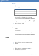
Enfinity
Solar-Log
1000/500/200
Installation 115 of 268
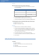
Connecting the inverters to each other (Solar-Log
500
, Solar-Log
1000
)
Connect using a 3 wire, shielded data cable.
Where to connect: on the upgraded RS485 interface
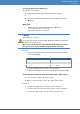
Procedure
1 Open the inverter as described in the inverter instructions.
2 Using the data cable connect terminals “Pin 2-RS485-A (+)”, “Pin 3-GND” and
“Pin 1-RS485-B (-)” of inverter 1 to the corresponding terminals on inverter 2.
3 Connect the other inverters to each other in the same way.
4 Terminate in the last inverter:
Set the jumper on the RS485 interface card to ON.
5 Close inverters.
Allocate communication address
Recommendation: Continuous numbering starting with 1.
Setting: Using the inverter operating display
Procedure: As set out in the inverter's instructions
Note:
When selecting inverters “APL monophase” must be selected.
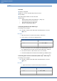
4.55 Enfinity
Overview
Interface integrated
2 RJ11 sockets inside the inverter.
4 pin wiring
Communication address must be allocated.
Work steps
• Switch off the inverters and the SolarLog™
• Connect inverters to the Solar Log™
• Connect the inverters to each other
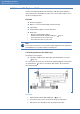
Connecting inverters to the Solar-Log™
The wiring is done using the
self-made, shielded 4 wire data cable and terminal block connector
(Page 15)
Where to connect: RJ11 socket on the inverter.