
Installation manual

Connecting the inverters
Santerno
86 of 268 Solar-Log
1000/500/200
Installation
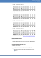
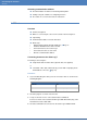
Allocating communication address
Recommendation: Continuous numbering starting with 1.
Setting: Using PC software for configuring inverters
Procedure: As set out in the inverter's instructions
4.37 Santerno
Overview
Interface integrated.
Where to connect: 9 pin socket on the outside of the housing floor.
2 pin wiring.
Communication address must be allocated.
Work steps
• Switch off the inverters and the SolarLog™; Page 17
• Install the RS485 interface in the inverter
• Connect inverters to the Solar-Log™
• Connect the inverters to each other
• Allocate communication address
Connecting inverters to the Solar-Log™
The wiring is done using the
ready-made Santerno data cable (optional extra; not supplied)
or
a shielded, 2 wire data cable made by yourself with a 9 pin plug and a
terminal block connector ( Page 15).
Procedure
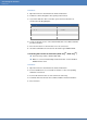
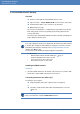
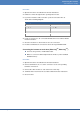
1 If you are fabricating the cable yourself, connect the wires as shown in the
following diagram:
Solar-Log™ terminal block connector
Inverter plug
Terminal
Pin
1
1 (A line)
4
2 (B line)
2 Insert the plug into socket A on the inverter.
3 If only one inverter is to be connected it must be terminated:
Connect socket A on the Santerno Solar Log™data cable to the plug of the
first Santerno inverter data cable.
4 Insert the terminal block connector into the Solar-Log™ RS485 socket.