MAKING MODERN LIVING POSSIBLE TripleLynx CN Reference Manual Three-phase – 10, 12.
Contents Contents 1. Safety and Conformity 5 Important Safety Information 5 Hazards of PV Systems 6 PV Load Switch 6 Conformity 7 2. Introduction 8 Introduction 8 List of Symbols 9 List of Abbreviations 9 Software Version 10 Manual History 10 Related Literature 10 3.
Contents Simulation of PV 42 6. Installation and Start-up 43 Installation Dimensions and Patterns 43 Mounting the Inverter 45 Removing the Inverter 47 Opening and Closing the Inverter 47 AC Grid Connection 50 PV Connection 51 Manual PV Configuration 52 7.
Contents Ethernet Communication 71 Start-up and Check of Settings 71 Master Mode 74 9. Web Server Quick Guide 76 Introduction 76 Supported Characters 76 Access and Initial Setup 76 Access via PC Ethernet Interface 76 Setup Wizard 77 Operation 81 Web Server Structure 81 Plant, Group and Inverter Views 82 Additional Information 84 10.
Contents Network Topology 4 104 L00410582-01_02
1. Safety and Conformity 1. Safety and Conformity 1 1.1. Important Safety Information All persons installing and servicing inverters must be: • Trained and experienced in general safety rules for work on electrical equipment • Familiar with local requirements, rules and regulations for the installation Safety information important for human safety. Violation of warnings may result in injury to persons or death. Information important for the protection of property.
1. Safety and Conformity Before installation: Check for damage to inverter and packaging. If in doubt, contact the supplier before installing the inverter. Installation: For optimum safety, follow the steps described in this manual. Keep in mind that the inverter has two voltage carrying sides; the PV input and the AC grid. Disconnecting the inverter: Before starting work on the inverter, switch off AC grid at the mains switch and PV using the PV load switch.
1. Safety and Conformity 1.4. Conformity 1 For approvals and certification information, go to the download area at • www.danfoss.com/solar, Approvals and Certifications • www.danfoss.cn/solar CGC marking - This certifies the conformity of the equipment with the regulations which apply in accordance with China General Certification Center, CGC/GF004:2011.
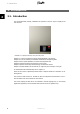
2. Introduction 2. Introduction 2 2.1. Introduction This manual describes planning, installation and operation of the full range of TripleLynx CN solar inverters. Illustration 2.1: TripleLynx CN 8 kW, 10 kW, 12.5 kW, 15 kW Chapters 3, 10 and 12 explain the functions and specifications of the inverter. Chapters 4, 5 and 12 describe pre-installation considerations and planning tasks. Chapters 6 and 7 explain installation of inverters and peripheral units.
2. Introduction 2.2. List of Symbols Symbol Explanatory note 1) Indicates reference to a section of the present manual. 2) Italics are also used to indicate an operation mode, e.g. operation mode Connecting. 1) Encloses a path of menu navigation. 2) Also used to enclose abbreviations such as [kW]. Indicates security level. Menu item accessible at plant level. Menu item accessible at group level or above. Menu item accessible at inverter level or above. Indicates a step within menu navigation.
2. Introduction 2.4. Software Version Always read the newest version of this manual. This manual is applicable for TripleLynx CN inverter software 1.0 and onwards. To see the software version go to [Status → inverter → serial no. and SW ver.] in the user interface. 2 2.5. Manual History This is the 1st version of the TripleLynx CN inverter reference manual. 2.6.
3. Description of the Inverter 3. Description of the Inverter 3.1. Variants The TLX TLX TLX TLX 3 TripleLynx CN inverter series comprises: CN CN+ CN Pro CN Pro+ Common features of the TripleLynx CN variants: • Output rating of 8 kW, 10 kW, 12.
3. Description of the Inverter 3.2. Mechanical Overview of inverter 3 Illustration 3.2: Mechanical Overview of Danfoss TripleLynx CN Inverter Item number 1 2 3 4 5 6 Part Name Wall Plate Condensing Cover Die Cast Aluminium-Heatsink DC-switch (PV load switch) Base plate Fan grill 80 x 80 mm 7 Fan, Sunon 80 x 80 x 38 8 9 10 11 12 13 14 15 16 17 18 19 20 21 Cover for 80 x 80 mm fan hole Aux.
3. Description of the Inverter 3.3. Description of the Inverter 3.3.1. Functional Overview The TripleLynx CN series comprises transformerless, 3 phase inverters with a high performance 3-level inverter bridge. For maximum flexibility the inverter has 2 or 3 separate inputs and equivalent number of MPP trackers (the number of trackers and inputs depend on the type). The inverter has an integrated residual current monitoring unit, insulation test functionality and an integrated PV load switch.
3. Description of the Inverter 3.3.2. Functional Safety The inverters in the TripleLynx CN range are designed according to the German Functional Safety VDE0126-1-1 (2006) standard. Single Fault Immunity The functional safety circuit is designed with two independent monitoring units, each having control of a set of grid-separation relays to guarantee single fault immunity. All functional safety circuits are tested during start-up to ensure safe operation for everyone.
3. Description of the Inverter Fail Safe (Red LED flashing) If the inverter detects an error in its circuits during the self-test (in connecting mode) or during operation, the inverter goes into fail safe mode. The inverter will remain in fail safe mode until PV power has been absent for a minimum of 10 minutes, or the inverter has been shut down completely (AC + PV). Refer to the section on Troubleshooting for further information. 3 3.3.3.
3. Description of the Inverter 2. • 3 Rate of change of frequency (ROCOF). The ROCOF values (positive or negative) are compared to the trip settings and the inverter ceases to energise the grid when the limits are violated. Residual current is monitored. The inverter ceases to energise the grid when: - the cycle RMS value of the residual current violates the trip settings for more than the duration of "clearance time" - a sudden jump in the DC value of the residual current is detected.
3. Description of the Inverter the grid. The local limits U1 and U2 are listed in the inverter grid codes at the www.danfoss.com/solar area, Approvals and Certifications. 3 Illustration 3.4: Grid Voltage Derating Current Derating At grid voltages lower than the nominal voltage, the inverter may derate to keep the output current within the specifications. Illustration 3.
3. Description of the Inverter 3 Illustration 3.6: Derating Temperature TripleLynx CN 8 kW TripleLynx CN 10 kW TripleLynx CN 12.5 kW PV current, per input 12 A (+2 %) 12 A (+2 %) 12 A (+2 %) Grid current, per phase 12 A (+2 %) 15 A (+2 %) 18 A (+2 %) Grid power, total 8000 W (+3 %) 10000 W (+3 %) 12500 W (+3 %) To avoid unintentional derating due to measurement inaccuracy, the values in brackets are TripleLynx CN 15 kW 12 A (+2 %) 22 A (+2 %) 15000 W (+3 %) added to the limits. Table 3.
3. Description of the Inverter TripleLynx CN inverter type No. of PV inputs TripleLynx CN 8 kW 2 TripleLynx CN 10 kW 2 TripleLynx CN 12.5 kW 3 TripleLynx CN 15 kW 3 Overall DC limit for the inverter 8.2 kW 10.3 kW 12.9 kW 15.5 kW Default DC power limit per PV input 5.15 kW 5.15 kW 5.15 kW 5.15 kW DC power limit per PV input 6.0 kW 6.0 kW 6.0 kW 6.0 kW Table 3.
3. Description of the Inverter 3 Illustration 3.7: Measured MPPT Efficiency for Two Different Ramp Profiles. 3.3.6. Efficiency The efficiency has been measured with a Yokogawa WT 3000 precision power analyser over a period of 250 sec., at 25 °C and 230 V AC grid. The efficiency graphs for the individual types in the TripleLynx CN inverter range are depicted below: Illustration 3.
3. Description of the Inverter 3 Illustration 3.9: Efficiency TripleLynx CN 10 kW Illustration 3.10: Efficiency TripleLynx CN 12.5 kW Illustration 3.
3. Description of the Inverter TPPV/UPV 5% 10 % 20 % 25 % 30 % 50 % 75 % 100 % EU 3 TripleLynx CN 8 kW 420 V 700 V 800 V 88.2 % 90.9 % 88.1 % 92.4 % 92.8 % 92.6 % 95.0 % 96.5 % 95.8 % 95.5 % 96.9 % 96.5 % 95.9 % 97.2 % 96.9 % 96.4 % 97.7 % 97.5 % 96.4 % 97.8 % 97.8 % 96.4 % 97.8 % 97.9 % 95.7 % 97.0 % 96.7 % TripleLynx CN 10 kW 420 V 700 V 800 V 87.3 % 90.4 % 89.1 % 90.6 % 92.9 % 92.5 % 94.4 % 96.0 % 95.6 % 95.2 % 96.6 % 96.3 % 95.7 % 97.0 % 96.7 % 96.6 % 97.7 % 97.5 % 96.9 % 97.8 % 97.8 % 97.1 % 97.
4. Change of Functional Safety Settings 4. Change of Functional Safety Settings 4.1. Functional Safety Settings Change of functional safety settings requires approval from the DNO. 4 The functional safety settings are defined by selection of grid code during the installation sequence. Later, change of functional safety settings may be required due to external conditions, for example persistent instability problems due to a weak AC grid.
4. Change of Functional Safety Settings Procedure for authorised technician: 1. Contact the service hotline to obtain a one-day level 2 password. 2. Access and change the grid code setting via the Web Server or the local display. 3. 4 - To change settings via the Web Server, use remote access. - The inverter logs the parameter change. Complete and sign the form ‘Change of Functional Safety Parameters’. - For local display access: Fill out the form by hand.
5. Requirements for Connection 5. Requirements for Connection 5.1. Pre-installation Guidelines The aim of this section is to provide general information about the use of the TripleLynx CN inverters. The section should be read before designing the PV system. The section covers AC grid connection requirements, e.g. the choice of AC cable protection, the design of the PV system, e.g. grounding, and finally the ambient conditions, e.g. ventilation. 5 5.2.
5. Requirements for Connection The selection of the mains circuit breaker rating depends on the wiring design (wire cross- sectional area), cable type, wiring method, ambient temperature, inverter current rating etc. Derating of the circuit breaker rating may be necessary due to self-heating or if exposed to heat. The maximum output current per phase can be found in the table.
5. Requirements for Connection 5 Illustration 5.2: TripleLynx CN 10 kW Cable Losses [%] versus Cable Length [m] Illustration 5.3: TripleLynx CN 12.5 kW Cable Losses [%] versus Cable Length [m] Illustration 5.4: TripleLynx CN 15 kW Cable Losses [%] versus Cable Length [m] Consider also the following when choosing cable type and cross-sectional area: - Ambient temperature - Layout type (inside wall, under ground, free air etc.
5. Requirements for Connection 5.2.2. Grid Impedance The grid impedance must correspond to the specifications to avoid unintended disconnection from the grid or derating of the output power. It is similarly important that proper cable dimensions are used to avoid losses. Additionally the no load voltage at the connection point must be taken into account. The maximum permitted grid impedance, as function of no load voltage for the TripleLynx CN inverter series, can be found in the following graph.
5. Requirements for Connection 5.3. Requirements for PV Connection Maximum Open Circuit Voltage The maximum open circuit voltage from the PV strings must not exceed the absolute maximum which the inverter is able to withstand. Check the specification of the open circuit voltage at the lowest PV module operating temperature.
5. Requirements for Connection 5 Illustration 5.6: MPP Area TripleLynx CN 8 kW. Above 800 V is reserved for derating.
5. Requirements for Connection 5 Illustration 5.7: MPP Area TripleLynx CN 12.5 kW. Above 800 V is reserved for derating.
5. Requirements for Connection 5 Illustration 5.8: MPP Area TripleLynx CN 10 kW and 15 kW. Above 800 V is reserved for derating. Reversed Polarity The inverter is protected against reversed polarity but it will not generate power until the polarity is corrected. Reversed polarity damage neither the inverter nor the connectors.
5. Requirements for Connection Remember to switch off the PV load switch before correcting polarity! PV to Earth Resistance The monitoring of the PV to earth resistance is implemented for all countries as supplying energy to the grid with too low a resistance could be harmful to the inverter and/or the PV modules.
5.
5. Requirements for Connection 5 Illustration 5.10: PV System Example 2 Illustration 5.9: PV System Example 1 ExString ample capacity, orientation and inclination 1 3 identical Connection point A Inverter Generator connection box x B External splitter * External parallel connection Yes 3 in parallel 2 3 identical x * When total input current exceeds 12A, external splitter is required.
5. Requirements for Connection 5 Illustration 5.12: PV System Example 4 Illustration 5.11: PV System Example 3 ExString ample capacity, orientation and inclination 3 4 3 different 1 different 2 identical Connection point A Inverter Generator connection box x x B External splitter * External parallel connection C Internal parallel connection in inverter Not permitted Not permitted for string 1. Optional for strings 2 and 3. * When total input current exceeds 12A, external splitter is required.
5. Requirements for Connection 5 Illustration 5.14: PV System Example 6 Illustration 5.13: PV System Example 5 ExString ample capacity, orientation and inclination 5 4 identical Connection point A Inverter Generator connection box x B External splitter * External parallel connection Yes 4 in parallel 6 4 identical x x Yes 3 in parallel 1 in series * When total input current exceeds 12A, external splitter is required.
5. Requirements for Connection 5 Illustration 5.16: PV System Example 8 Illustration 5.15: PV System Example 7 ExString ample capacity, orientation and inclination 7 8 6 identical 4 identical Connection point A Inverter Generator connection box x x x B External splitter * External parallel connection C Internal parallel connection in inverter Required Required * When total input current exceeds 12A, external splitter is required.
5. Requirements for Connection PV Cable Dimensions and Layout As a rule of thumb the power loss in the PV cables should not exceed 1 % of nominal value in order to avoid losses. For an array of 5000 W at 700 V, this corresponds to a maximum resistance of 0.98 Ω. Assuming aluminium cable is used (4 mm2 → 4.8 Ω/km, 6 mm2 → 3.4 Ω / km), the maximum length for a 4 mm2 cable is approximately 200 m and for a 6 mm2 cable approximately 300 m.
5. Requirements for Connection 5 System type Max KPVAC: Tracker systems Fixed systems with optimal conditions: Close to ideal orientation (between SW and SE) and inclination (more than 10°) Fixed systems with semi-optimal conditions: Orientation or inclination exceed the above mentioned limits. Fixed systems with sub-optimal conditions: Orientation and inclination exceed the above mentioned limits. 1.05 1.
5. Requirements for Connection 5.3.2. Thin Film The use of TripleLynx CN inverters with thin film modules has been approved by some manufacturers. Declarations and approvals can be found at www.danfoss.com/solar. If no declaration is available for the preferred module it is important to obtain approval from the module manufacturer before installing thin film modules with the inverters. The power-circuit of the inverters is based on an inverted asymmetrical boost converter and bipolar DC-link.
5. Requirements for Connection Note: PELV protection is effective up to 2000 m above sea level only. Other factors like higher irradiation should also be taken into account. The heat-sink should be cleaned regularly and checked for dust and blocking elements once a year. Optimise reliability and lifetime by mounting the inverter in a location with low ambient temperature. 5 Note: For calculation of ventilation, consider a max. heat dissipation of 600 W per inverter. 5.3.5.
6. Installation and Start-up 6. Installation and Start-up 6.1. Installation Dimensions and Patterns Avoid constant stream of water. Avoid direct sunlight. 6 Ensure adequate air flow. Ensure adequate air flow. Mount on non-flammable surface. Mount upright on vertical surface. Prevent dust and ammonia gases.
6. Installation and Start-up 6 Illustration 6.1: Safe Distances Observe these distances when installing one or more inverters. One row mounting is recommended. Contact the supplier for information on mounting in more rows. Illustration 6.2: Wall Plate Note: Use of the wall plate delivered with the inverter is mandatory. Use screws that can safely carry the weight of the inverter. The inverter must be aligned and it is important that the inverter is accessible at the front to allow room for servicing.
6. Installation and Start-up 6.2. Mounting the Inverter For safe handling of the inverter, two people must carry the unit, or a suitable transport trolley must be used. Safety boots must be worn. Tilt the inverter as shown in the illustration and place the top of the inverter against the mounting bracket. Use the two guides (1) at the top plate to control the inverter horizontally. 6 Illustration 6.
6. Installation and Start-up Place the lower part of the inverter against the mounting bracket. 6 Illustration 6.5: Place Inverter in Mounting Bracket Lower (4) the inverter and make sure that the hook of the inverter base plate is placed in the lower part of the mounting bracket (5). Check that it is not possible to lift the bottom of the inverter away from the mounting bracket. (6) Fasten the screws on either side of the wall plate to secure the inverter. Illustration 6.
6. Installation and Start-up 6.3. Removing the Inverter Loosen the locking screws on either side of the inverter. Removal is performed in the reverse order of mounting. With a firm grip at the lower end of the inverter, lift the inverter approximately 20 mm vertically. Pull the inverter slightly away from the wall. Push upwards at an angle until the wall plate releases the inverter. Lift the inverter away from the wall plate. 6.4.
6. Installation and Start-up Push the front cover upwards. When a slight resistance is felt, give the front cover a tap on the bottom to snap it into holding position. It is recommended to use the holding position instead of dismounting the front cover completely. 6 Illustration 6.8: Open the Inverter To close the inverter, hold on to the lower end of the front cover with one hand and give it a tap on the top until it falls into place. Guide the front cover into place and fasten the two front screws.
6. Installation and Start-up 6 Illustration 6.10: Fasten Front Screws and Ensure Proper PE Connection The two front screws are the PE connection to the front cover. Make sure that both screws are mounted and fastened with the specified torque.
6. Installation and Start-up 6.5. AC Grid Connection 6 Illustration 6.11: AC Cable Wire Strip Legend 1 Blue cable - Neutral 2 Yellow/green cable - Earth The illustration shows the stripping of insulation of all 5 wires of the AC cable. The length of the PE wire must be longer than the mains and neutral wires. Illustration 6.12: AC Connection Area 50 1. Verify the inverter matches the grid-voltage. 2. Release main circuit breaker and make precautions to prevent reconnection. 3.
6. Installation and Start-up 7. All wires must be properly fastened with the correct torque. See the section Technical Data, Torque Specifications for Installation. 8. Close the front cover, and remember to verify that both front screws are applied with the correct torque to obtain PE connection. 9. Close main circuit breaker. For safety, check all wiring. Connecting a phase wire to the neutral terminal may permanently damage the inverter. Do not remove the short circuit bridge at (1). 6.6.
6. Installation and Start-up When unmated the MC4 connectors are not IP54. The intrusion of moisture may occur in the following situations: 1. The inverter runs in Master/Slave operation and only one or two PV inputs are in use. In this case, the other inputs are not connected to PV and they are therefore open to intrusion. 2. Not all PV inputs are connected. 3. PV connectors are not fitted; for example in case of disconnection of parts of a PV plant over a longer period of time.
7. Connection of Peripheral Units 7. Connection of Peripheral Units 7.1. Overview Auxiliary interfaces are provided via PELV circuits and are safe to touch during normal operation. AC and PV must, however, be turned off before installation of peripheral units. Note: For wiring details, refer to the section Auxiliary Specifications.
7. Connection of Peripheral Units 7 Illustration 7.1: Auxiliary Connection Area Communication board (1-4) Cable glands (5) EMC clamps (6) 7.2. Installation of Peripheral Cables To ensure fulfilment of the IP enclosure rating, correctly mounted cable glands are essential for all peripheral cables. Hole for cable gland The base plate of the inverter is prepared for cable glands M16 (6 pcs.) and M25 (2 pcs.). Holes and threads are pre-drilled and shipped with blind plugs. Illustration 7.
7. Connection of Peripheral Units 1. M16: Other peripheral units (sensors, alarm outputs and RS485 peripheral which interface the terminal block). 2. M25: For RS485 and Ethernet peripheral units which apply RJ45 plugs. 7.2.1. RS485 Peripheral and Ethernet Units which apply RJ45 1. Unscrew the blind plugs. 2. Place the M25 cable gland in the cabinet, add the nut and fasten the cable gland. 3. Unscrew the cap of the cable gland and slide it over the cable(s). 4.
7. Connection of Peripheral Units • Thin shielded cable (cable shield is folded back over the jacket) • Thick shielded cable (> approx. 7 mm) • Unshielded cable (alarm output) 4. Fasten the cable clamp screw to secure it and check that the cable shield is mechanically fixed. 5. Fasten the cable gland cap. Terminal block: 1. Strip off insulation from the wires (approx. 6-7 mm). 2. Insert the wires in the terminal block and fasten the screws to secure them properly. 7 Illustration 7.
7. Connection of Peripheral Units Temperature sensor input Ambient temperature Function Readout via display or Web Server and/or communication (logging) Readout via display or Web Server and/or communication (logging) Internal use for temperature correction of irradiation measurement PV module temperature Irradiation sensor temperature Table 7.1: Temperature Sensor Inputs The supported temperature sensor type is PT1000.
7. Connection of Peripheral Units 7 Illustration 7.9: Placement of GSM Modem and GSM Antenna 1. Communication board 2. GSM modem 3. External mounting position for GSM antenna 4. Internal GSM antenna For more details, refer to the GSM Manual. 7.6. RS485 Communication RS485 communication supports the following Danfoss peripheral units: • ComLynx Datalogger • ComLynx Weblogger For layout of the RS485 interface, see the section Installation of Peripheral Cables.
7. Connection of Peripheral Units The Windows™ based software program has a user-friendly interface that enables key parameters of a plant in to be viewed in graphic form. Transmission range is up to 1000 m and the maximum distance between the Datalogger and the PC is 12 metres. For a more detailed overview, refer to the data sheet of the Datalogger, and for more detailed information refer to the Datalogger User Manual.
8. User Interface 8. User Interface 8.1. Integrated Display Unit Note: The display activates up to 10 seconds after power up. The integrated display on the inverter front gives the user access to information about the PV system and the inverter. The display has two modes: Normal Power saving The display is in use After 10 min. of no display activity the back light of the display turns off to save power.
8. User Interface Three predefined security levels filter user access to menus and options. Security levels: • Level 0: End-user, no password is needed • Level 1: Installer / service technician • Level 2: Installer / service technician (extended). When logged on to the Web Server as Admin, access is at security level 0. Subsequent user accounts created provide access to a predefined subset of menus, according to user profile.
8. User Interface 8.1.3. Status Menu Structure - Status Display Functions [0] Ambient Conditions [0] Irradiance: 1400W/m2 [0] PV module temp: 100 oC [0] Ambient temp: 20oC [0] Irr. sensor temp: 32 oC [0] Photovoltaic [0] Present values [0] PV input 1 [0] Voltage: 1000V [0] Current: 15.0 A [0] Power 10000 W [0] PV input 2 [0] Voltage: 1000V [0] Current: 15.0 A [0] Power 10000 W [0] PV input 3 [0] Voltage: 1000V [0] Current: 15.
8. User Interface Menu Structure - Status - Continued Display Functions [0] AC-grid [0] Present Values [0] Phase 1 [0] Voltage: 250 V [1] 10 min. mean: 248 V [1] L1-L2: 433 V [0] Current: 11.5 A [1] DC-cont of current: 125 mA [0] Frequency: 50 Hz [0] Power: 4997 W [1] Apparent P. (S): 4999 VA [1] Reactive P. (Q): 150 VAr [0] Phase 2 [0] Voltage: 250 V [1] 10 min. mean: 248 V [1] L2-L3: 433 V [0] Current: 11.5 A [1] DC-cont of current: 125 mA [0] Frequency: 50 Hz [0] Power: 4997 W [1] Apparent P.
8.
8. User Interface 8.1.4.
8. User Interface Menu Structure - Production Log - Continued Display Functions Description [0] Time stamps [0] Installed: 30-12-99 Date of first grid connection [0] Power down: 21:00:00 When the inverter last changed to operation mode off grid [0] Prod.
8. User Interface 8.1.5. Setup Menu Structure - Setup Display Functions [0] External Alarm [0] Stop Alarm [0] Test Alarm [0] Alarm state: Disabled Description Only applicable if external alarm is connected Stop alarm Includes testing red LED on front 009 s alarm time limit. If 0, the alarm will be active until fixed [0] Alarm time-out: [0] Setup details [0] Language: [2] Grid code: [2] Safety affecting settings [2] 10 min. mean voltage [2] Avg.
8. User Interface Menu Structure - Setup - Continued Display Functions [0] Environment* [0] CO2 emission factor: [0] 0.5 kg/kWh [0] Remuneration per kWh: [0] 44.42 ct/kWh Description Value to be used for total CO2 saved calculation Value to be used for total revenue calculation A value used as an offset from the current production value when calculating the yield.
8. User Interface 8.2. Overview of Event Log The event log menu found under Log displays the last event which has occurred. Latest event Example: The latest event is of type “Grid” and the specific event ID is “29”. This can be used to diagnose the problem. See the section on Troubleshooting for more information on specific events. Latest event is set to 0 once an event is cleared. 8 Illustration 8.
8. User Interface 8.3. Peripheral Units Setup 8.3.1. Sensor Setup This section describes the final step of configuring the sensor inputs using the display or the Web Server. Go to the Calibration menu under Setup [Setup → Calibration] and choose the sensor to be configured. Temperature Sensor The temperature sensor inputs for the PV module temperature and the ambient temperature may be calibrated using an offset ranging from -5.0 to 5.0 °C. Enter the correct values for the sensors under the Temp.
8. User Interface The alarm output can also be configured via the integrated Web Server. For details, refer to the Web Server User Manual. 8.3.3. Communication Channel This menu item is available for TLX CN Pro and TLX CN Pro+ only. Selection of a communication channel is the first step in configuration of email transmission and FTP upload. To select communication channel: • Use the display of the master inverter. • Go to [Setup → Communication setup → Communication channel].
8. User Interface Note: For the TLX CN Pro and TLX CN Pro+ inverters the first start-up and check of settings can also be performed via the integrated Web Server. For further details, refer to the Web Server User Manual. The inverter is shipped with a predefined set of settings for different grids. All grid specific limits are stored in the inverter and must be selected at installation. It is always possible to see the applied grid limits in the display.
8. User Interface Set date as prompted by the display. Press 'OK' to select. Press ‘ ▲ ’ to scroll up through the numbers. Select by pressing 'OK'. Chinese date format: yyyy-mm-dd. Illustration 8.6: Set Date Enter the amount of installed PV power for each of the PV inputs. When two or more PV inputs are connected in parallel, each PV input in the parallel group must be set to the total amount of PV power installed to that group divided by the number of parallel inputs.
8. User Interface Confirm the choice by selecting the grid code again and press 'OK’. The settings for the chosen grid code have now been activated. Illustration 8.9: Confirm Grid Code Selection Correct selection of grid code is essential to comply with local and national standards. 8 Note: If the two grid code selections do not match they will be cancelled and it will be necessary to redo the selections.
8. User Interface inverters in the network, enabling easy commissioning and data management of larger networks. Replication can be performed once, prior to defining the grid code in follower inverters. To enable Master mode go to the Inverter details menu [Setup → Inverter details → Master mode] and set Master mode to Enabled. Ensure that no other master inverters are present in the network prior to carrying out this action.
9. Web Server Quick Guide 9. Web Server Quick Guide 9.1. Introduction These instructions describe the TLX CN Pro Web Server, which facilitates remote access to the inverter. The Web Server is available in TLX CN Pro and TLX CN Pro+ inverters only. Refer to the download area at www.danfoss.com/solar for the newest instructions. 9.2. Supported Characters For all language versions, the Web Server software supports characters compatible with Unicode.
9. Web Server Quick Guide Illustration 9.1: Product Label 7. At initial startup of the inverter, the inverter runs a setup wizard. 9.3.2. Setup Wizard Step 1 of 7: Master setting To set up a master inverter, click on [Set this inverter as master]. • A scan runs to identify inverters in the network. • A pop-up window shows the inverters successfully identified. Click [OK] to confirm that the correct number of inverters has been found. 9 Illustration 9.
9. Web Server Quick Guide Illustration 9.3: Step 2 of 7: Display Language To change the language setting later, refer to Setup, Setup Details. Step 3 of 7: Time and date Enter • time in 24-hour format • date • time zone Accuracy is important, because date and time are used for logging purposes. Adjustment for daylight savings is automatic. 9 Illustration 9.4: Step 3 of 7: Time and Date To change these settings later, refer to Setup, Inverter details, Set Date and Time.
9. Web Server Quick Guide Illustration 9.5: Step 4 of 7: Installed Power To change the installed power, refer to Setup, Calibration, PV Array. Step 5 of 7: Grid code Select the grid code to match the location of the installation. To meet medium-voltage grid requirements select a grid code ending in MV. • 9 The default setting is [undefined]. Select the grid code again, to confirm. • The setting is activated immediately. Correct selection is essential to comply with local and national standards.
9. Web Server Quick Guide Note: If the initial and confirmation settings are different, • grid code selection is cancelled • the wizard recommences step 5 If initial and confirmation settings match, but are incorrect, contact service.
9. Web Server Quick Guide Illustration 9.8: Step 7 of 7: Inverter startup To change the setup later, access the inverter via the integrated web interface or the display, at inverter level. • To change the name of the inverter, go to [Setup → Inverter details] • To enable master mode, go to [Setup → Inverter details] 9.4. Operation 9.4.1. Web Server Structure 9 The Web Server overview is structured as follows. Illustration 9.9: Overview 1.
9. Web Server Quick Guide 2. 3. 9 • Click on the plant name to display the plant view. • Change the plant name at [Setup → Plant details]. Group menu: Displays groups of inverters: • Inverters join group 1 by default • Click on a group name to display the group view, and a list of inverters in the group. • Change the group name via [Setup → Inverter details] in the inverter view. Group members: Displays the inverter names in the group currently selected.
9. Web Server Quick Guide Illustration 9.
9. Web Server Quick Guide 9.5.
10. Ancillary Services 10. Ancillary Services 10.1. Introduction Ancillary services comprise inverter functionalities which aid transport of power on grids. Which ancillary services are required for a given PV system are determined by the point of common coupling (PCC) and the grid type to which the system is connected. The PCC is the point where the PV system is connected to the public electricity grid.
10. Ancillary Services Note: Check local legal requirements before changing settings for ancillary services. 10.2. Power Level Adjustment The inverter supports Power Level Adjustment (PLA) as required by the German EEG for systems above 100 kW. To control the functionality, a grid management interface is necessary. This is available via third-party suppliers for all TripleLynx CN inverters, or via the Danfoss Grid Management Box for TLX CN Pro and TLX CN Pro+ inverters.
10. Ancillary Services Illustration 10.2: Medium-Voltage Primary Frequency Control The increase in output power follows a time ramp T (time gradient). The frequency-power gradient S and the time ramp T are adjustable. The frequency limit values f1 and f2 (activation and deactivation frequencies) differ internationally. For local values of f1 and f2, go to the download area at www.danfoss.com/solar, Approvals and Certifications. 10.4.
10. Ancillary Services • Constant reactive power Q • Constant power factor PF Off The inverter will not use any internal setpoint for reactive power, but an external setpoint source can be used. Danfoss TLX CN+ inverters support a number of third-party grid management units for managing reactive power. Constant Reactive Power Q The inverter will generate a fixed level of reactive power, specified as a percentage of the inverter’s nominal apparent power (S).
10. Ancillary Services 10.4.2. Managing Reactive Power Using TLX CN+ The TLX CN+ inverter provides controlled reactive power by using an external setpoint source, i.e. a third-party product. Note: For TLX CN+ inverters: Inverter control of reactive power is only possible for medium-voltage or custom grid codes. Illustration 10.3: Example: Managing Reactive Power Using TLX CN+ 1 DNO interface (radio receiver) 2 Third-party product 10.4.3.
10. Ancillary Services Nominal Plant AC power The nominal apparent power of the entire plant must be entered here in order for the master inverter to make the correct scaling of the reactive power generated. Set reference value under: • Grid management box: The external reference for reactive power for the whole plant is received via the Danfoss Grid Management Box. • Reactive power, Q, and Power factor, PF The master inverter sets the entered values of Q or PF to all inverters in the plant.
10. Ancillary Services With Relay input, the reference source is received via four discrete signals (K1-K4). This allows for 16 different combinations and each one can be configured for a specific value of Q or PF and power reduction (PLA). Note: For more information, refer to the Web Server User Manual and the Grid Management Box Manual. 10.4.5. Theory The principle in generating reactive power is that the phases between the voltage and the current are shifted in a controlled way.
10. Ancillary Services 1. To help prevent a complete voltage black-out and stabilise the voltage in the grid. 2. To increase the energy delivered to the AC grid. The inverter has a high immunity against voltage disturbances as depicted below. 10.5.1. Example How FRT works The diagram below shows the requirements to be followed by FRT. • Above line 1 For voltages above line 1, the inverter must not disconnect from the grid during FRT, under any circumstances.
10. Ancillary Services Parameters related to FRT) These parameters are set automatically upon selecting the grid code. Parameter FRT upper threshold level FRT lower threshold level Static reactive power, k Description Upper grid voltage magnitude for engaging a high-voltage FRT Lower grid voltage magnitude for engaging a low-voltage FRT Ratio between additional reactive current to be injected during the FRT and the depth of the sag, k= (ΔIB/IN) / (ΔU/UN) ≥ 2.0 p.u.
11. Service and Repair 11. Service and Repair 11.1. Troubleshooting This guide is intended to quickly diagnose and, if possible, remedy an error affecting the TripleLynx CN inverter. Go to the Log menu and enter the Eventlog menu. The latest event registered by the inverter, as well as a list of the 20 most recent events, is shown here. When the inverter enters the On grid mode, the most recent event is cleared and is shown as 0.
11.
11.
11. Service and Repair 11.2.2. Cleaning the Heatsink Clean the heatsink using pressurised air, a soft cloth or a brush. For correct operation and long service life, ensure free air circulation - around the heatsink at the rear of the inverter - to the fan at the inverter base Do not touch the heatsink during operation. Temperature can exceed 70 °C. Note: Do not cover the inverter. Do not use a water hose, aggressive chemicals, cleaning solvents or strong detergents to clean the inverter.
12. Technical Data 12. Technical Data 12.1. Technical Data Nomenclature 1) Pac,r Vac,r Iacmax cosphiac,r fr Vdc,r Vmppmin Vmppmax Vdcmax Vdcstart Vdcmin Idcmax 12 Parameter AC Nom. power AC Reactive power range AC voltage range (P-N) Nominal current AC Max. current AC AC current distortion (THD %) Power factor at 100 % load Controlled power factor range “Connecting” power loss Night-time power loss (off grid) Grid frequency DC Nominal power DC Max.
12. Technical Data 1) 2) 3) 4) 5) According to FprEN 50524. For fixed systems with semi-optimal conditions. At identical input voltages. At unequal input voltages, Vmppmin can be as low as 250 V depending on total input power. SPL (Sound Pressure Level) at 1.5m. Grid Management Box (TLX CN Pro and TLX CN Pro+) or third-party product. 12.2. Norms and Standards Refer to Chapter 1, section Conformity for details. 12.3.
12. Technical Data 12.4. Torque Specifications for Installation Illustration 12.1: Overview of Inverter with Torque Indications, 1-3 12 Illustration 12.2: Overview of Inverter with Torque Indications, 4-7 1 2 3 4 5 6 7 Parameter Terminal blocks (large) Terminal blocks (small) PE M16 M25 Front screw Locking screw Screwdriver Straight slot 1.0 x 5.5 mm Straight slot 1.0 x 5.5 mm Straight slot 1.0 x 5.5 mm SW 19 mm SW 30 mm TX 30 TX 30 Table 12.
12. Technical Data 12.5. Auxiliary Interface Specifications Parameter Serial Communication Common cable specification RJ45 (2 pcs.) connectors Terminal block Parameter Details Cable jacket diameter (⌀) Cable type Cable Characteristic Impedance Max. cable length Wire gauge Cable shield termination Maximum wire gauge Cable shield termination Max.
12. Technical Data 1) Max. number of inverters are 100. If GSM modem is used for portal upload, the amount of inverters in a network is limited to 50. 2) For outdoor use, we recommend outdoor burial type cable (if buried in the ground) for both Ethernet and RS485. 3) Third input is used for compensation of the irradiation sensor. 4) The number of inverters to be connected in the RS485 network depend on which peripheral device is connected.
12. Technical Data RS485 Terminate the RS485 communication bus at both ends. To terminate the RS485 bus: • Connect Bias L to RX/TX B • Connect Bias H to RX/TX A The RS485 address of the inverter is unique, and defined at the factory. Illustration 12.4: RS485 Communication Detail - Cat 5 T-568A Pinout RS485 1. GND 2. GND 3. RX/TX A (-) 4. BIAS L 5. BIAS H 6. RX/TX B (+) 7. Not connected 8.
12. Technical Data 12.5.1. Network Topology The inverter has two Ethernet RJ45 connectors enabling the connection of several inverters in a line topology as an alternative to the typical star topology. The two ports are similar and may be used interchangeably. For RS485, only linear daisy chain connections can be used. Note: Ring topology is not allowed. 12 Illustration 12.
Danfoss Solar Inverters A/S Ulsnaes 1 DK-6300 Graasten Denmark Tel: +45 7488 1300 Fax: +45 7488 1301 E-mail: solar-inverters@danfoss.com www.solar-inverters.danfoss.com Danfoss can accept no responsibility for possible errors in catalogues, brochures and other printed material. Danfoss reserves the right to alter its products without notice.